
User guide


Configuring for Test Testing the Components
184
pmp-0229 (Mar 2013)
Default Module Configuration
From the factory, the AP, SM, and BH are all configured to not transmit on any frequency. This
configuration ensures that you do not accidentally turn on an unsynchronized module. Site
synchronization of modules is required because
• modules
o cannot transmit and receive signals at the same time.
o use TDD (Time Division Duplexing) to distribute signal access of the downlink and
uplink frames.
• when one module transmits while an unintended module nearby receives signal, the
transmitting module may interfere with or desense the receiving module. In this context,
interference is self-interference (within the same network).
Component Layout
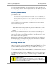
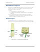
As shown in Figure 55, the base cover of the module snaps off when you depress a lever on the
back of the base cover. This exposes the Ethernet and GPS sync connectors and diagnostic LEDs.
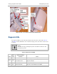
Figure 55: Base cover, detached and attached, FSK module
Et
h
er
n
e
t
C
ab
le
B
a
s
e
C
o
v
e
r
R
e
l
e
a
se
L
e
v
e
r
B
a
s
e
C
o
v
e
r
Ethernet
Cable
RJ45
Connector
Connection
LEDs
Base Cover
RJ11
Connector