
User guide


Diagramming Network Layouts Engineering Your RF Communications
156
pmp-0229 (Mar 2013)
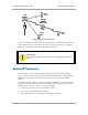
6. Assess whether the link achieves good Power Level and Jitter values.
NOTE: The received Power Level is shown in dBm and should be maximized.
Jitter, where a value is present, should be minimized. However, better/lower jitter
should be favored over better/higher dBm. For historical reasons, RSSI is also
shown and is the unitless measure of power. The best practice is to use Power
Level and ignore RSSI, which implies more accuracy and precision than is
inherent in its measurement.
7. Access the Link Capacity Test tab in the Tools web page of the module.
8. Assess whether the desired links for this module achieve
◦ uplink efficiency greater than 90%.
◦ downlink efficiency greater than 90%.
9. If the desired links fail to achieve any of the above measurement thresholds, then
a. access the module by direct Ethernet connection.
b. access the Radio tab in the Configuration web page of the module.
10. In the Transmitter Output Power parameter, increase the setting.
11. Click Save Changes.
12. Click Reboot.
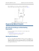
Avoiding Other Interference
Where signal strength cannot dominate noise levels, the network experiences
• bit error corrections.
• packet errors and retransmissions.
• lower throughput (because bandwidth is consumed by retransmissions) and high latency (due
to resends).
Be especially cognitive of these symptoms for 900-MHz links. Where you see these symptoms,
attempt the following remedies:
• Adjust the position of the SM.
• Deploy a band-pass filter at the AP.
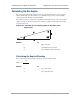
• Consider adding a remote AP closer to the affected SMs. (See Deploying a Remote AP on
Page 150.)
Certain other actions, which may seem to be potential remedies, do not resolve high noise level
problems:
• Do not deploy an omnidirectional antenna.
• Do not set the antenna gain above the regulated level.
• Do not deploy a band-pass filter in the expectation that this can mitigate co-channel
interference.