
User guide


Diagramming Network Layouts Engineering Your RF Communications
154
pmp-0229 (Mar 2013)
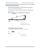
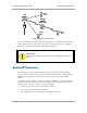
Where the SM simply serves as a relay, you must use a straight-through RJ-45
female-to-female coupler, and wire the SM to the remote AP as shown in Figure 47.
Figure 47: Remote AP wired to SM that serves as a relay
Diagramming Network Layouts
Accounting for Link Ranges and Data Handling
Requirements
For aggregate throughput correlation to link distance in both point-to-multipoint and
point-to-point links, see
• Link Performance and Encryption Comparisons on Page 62.
• all regulations that apply in your region and nation(s).
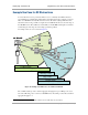
Avoiding Self Interference
For 5.2-, 5.4-, and 5.7-GHz modules, 20-MHz wide channels are centered every 5 MHz. For 2.4-
GHz modules, 20-MHz wide channels are centered every 2.5 MHz. For 5.4-GHz OFDM modules,
10-MHz wide channels can be centered every 0.5 MHz. This allows you to customize the channel
layout for interoperability where other equipment is co-located, as well as select channels with the
least background interference level.