
User guide


Canopy System User Guide
pmp-0229 (Mar 2013)
123
Chapter 12: Engineering Your RF
Communications
Before diagramming network layouts, the wise course is to
• anticipate the correct amount of signal loss for your fade margin calculation (as defined
below).
• recognize all permanent and transient RF signals in the environment.
• identify obstructions to line of sight reception.
Anticipating RF Signal Loss
The C/I (Carrier-to-Interference) ratio defines the strength of the intended signal relative to the
collective strength of all other signals. Standard modules typically do not require a C/I ratio
greater than
• 3 dB or less at 10-Mbps modulation and −65 dBm for 1X operation. The C/I ratio that you
achieve must be even greater as the received power approaches the nominal sensitivity (−85
dBm for 1X operation).
• 10 dB or less at 10-Mbps modulation and −65 dBm for 2X operation. The C/I ratio that you
achieve must be even greater as the received power approaches the nominal sensitivity (−79
dBm for 2X operation).
• 10 dB or less at 20-Mbps modulation.
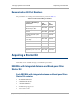
Nominal receive sensitivity in PMP 400 Series modules is as follows:
• −89 dBm for 1X operation
• −78 dBm for 2X operation
• −70 dBm for 3X operation
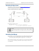
Understanding Attenuation
An RF signal in space is attenuated by atmospheric and other effects as a function of the distance
from the initial transmission point. The further a reception point is placed from the transmission
point, the weaker is the received RF signal.