
User guide


Release9.5ReleaseNotes
Issue2,October2009 Page68
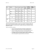
Band Antenna
Variable
d
(calcu-
lated)
Recom-
mended
Separation
Distance
Power
Compliance
Margin
P G
S
5.7 GHz integrated 0.2 W
(23 dBm)
5.0
(7 dB)
10
W/m
2
9 cm 20 cm
(8 in)
5
integrated plus
reflector
0.2 W
(23 dBm)
316
(25 dB)
10
W/m
2
71 cm 1.5 m
(5 ft)
4.5
Integrated plus
LENS
0.2 W
(23 dBm)
50
(17 dB)
1
W/m
2
28 cm 50 cm
(12 in)
3.13
5.4 GHz
OFDM
Integrated, 17 dBi 0.05 W
(10 dBm)
50
(17 dB)
10
W/m
2
6 cm 20 cm
(8 in)
10
Connectorized, 17
dBi
0.05 W
(10 dBm)
50
(17 dB)
10
W/m
2
6 cm 20 cm
(8 in)
10
4.9 GHz
OFDM
Integrated, 17 dBi 0.063 W
(18 dBm)
40
(16 dB)
10
W/m
2
14 cm 20 cm
(8 in)
2
Connectorized, 17
dBi
0.063 W
(18 dBm)
40
(16 dB)
10
W/m
2
14 cm 20 cm
(8 in)
2
The Recommended Separation Distance is chosen to give significant compliance margin in all
cases. It is also chosen so that a given item (bare module, reflector, or LENS) always has the
same distance, regardless of frequency band, to simplify remembering and following exposure
distances in the field.
These are conservative distances:
They are along the beam direction (the direction of greatest energy).
Exposure to the sides and back of the module is significantly less.
They meet sustained exposure limits for the general population (not just
short-term occupational exposure limits), with considerable margin.
In the reflector cases, the calculated compliance distance d is greatly
overestimated because the far-field equation models the reflector as a point
source and neglects the physical dimension of the reflector.