
Brukerveiledning
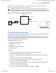
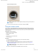
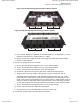
Table Of Contents
- Exhibit D - Tune-Up Procedure-User Manual-front
- Pages from MN003557A01-AL_enus_SLR1000_Repeater_Basic_Service_and_Installation_Manual_NAG
- Pages from Exhibit D - Tune-Up Procedure-User Manual-d2header
- MN003581A01_AA_enus_MOTOTRBO_SLR_1000_Repeater_Quick_Start_Guide-modified

5 In the tree view, select TX, then select Tx Audio Level.
6 Enter the tuning frequency into the Communication Analyzer (the value displayed in the Tuner
application under the heading Frequency Points.
7 To key up the repeater, click PTT Toggle.
8 Adjust the softpot value until the desired receive audio level is achieved at Pin 7 (in reference to
ground) on the Aux connector.
The ground connection provided by the Aux connector is Pin 4.
NOTE: The Tuner aligns this parameter in a 12.5 kHz channel spacing, so 60% is 1.5
kHz of deviation. If Radio Management (RM) is set for 25 kHz operation, the repeater
automatically scales the deviation by a factor of two when it is outside the Tuner
application.
9 To de-key the repeater, click PTT Toggle.
10 To save the new tuned softpot value into the repeater codeplug, click Write.
8.7
Modulation Limit Alignment
Modulation is a change or alteration in the signal. Any aspect of the signal can be changed, such as
amplitude, frequency, phase, timing or repetition rate of pulses. Aligning the modulation limit sets the
RF carrier wave of the frequency bandwidth of the SLR 1000 Repeater.
NOTE: A modulation limit alignment is always required when the repeater is in digital mode.
This alignment is not required if the repeater is used in repeat mode.
8.7.1
Tuning the Modulation Limit (with no Tx Data and no PL)
Prerequisites: Obtain the following:
• Wattmeter (Communication Analyzer)
• Service monitor or counter
• 20 dB pad
• Standard Type A to Type B USB cable
• Personal computer
Procedure:
1 Connect the repeater antenna port to the attenuation pad, if necessary, before connecting to the
Communication Analyzer.
2 Power the repeater from a DC source.
3 Apply a 1 kHz signal at 1.2 Vrms to Pin 1 of the Aux connector.
Signal ground is Pin 4 of the Aux connector.
4 Launch the Tuner application.
5 To read the softpot values, click Read.
6 In the tree view, select TX, then select Modulation Limit.
7 Enter the tuning frequency into the Communication Analyzer (the value displayed on the Tuner
application).
8 To key up the repeater, click PTT Toggle.
MN003557A01-AL
Chapter 8 : SLR 1000 Programming and Tuning
68
Applicant: Motorola Solutions
Equipment Type: ABZ99FT3096B / 109AB-99FT3096B
Tune-Up Procedure
Exhibit D1 5 of 11