
Brukerveiledning
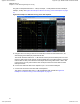
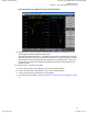


Table Of Contents
- Exhibit D - Tune-Up Procedure-User Manual-front
- Pages from MN003557A01-AL_enus_SLR1000_Repeater_Basic_Service_and_Installation_Manual_NAG
- Pages from Exhibit D - Tune-Up Procedure-User Manual-d2header
- MN003581A01_AA_enus_MOTOTRBO_SLR_1000_Repeater_Quick_Start_Guide-modified

Figure 26: Example for LOW Port Tuning of the UHF Duplexer
d Using the three T10 tuning screws on the HIGH side, tune M1 for best insertion loss, s21,
while keeping the isolation (M2) better than 65 dB.
The results should be better than -1.7 dB. Shorter screws (turned clockwise) are for a lower
frequency and longer screws (turned counterclockwise) are for a higher frequency. Keep all
three screws for each port at about the same depth when tuning each section. Later in this
tuning process you may notice that the three HIGH port screws are shorter than the three
LOW port screws.
4 View the rejection of each port, as follows:
a Connect the LOW side of the duplexer to port 1 on the network analyzer.
b Connect the HIGH side of the duplexer to port 2 on the network analyzer.
c Connect a 50 ohm load to the ANT port on the duplexer.
d The results should be similar to Figure 27: Rejection of Each Port for UHF Duplexer
on page
74
MN003557A01-AL
Chapter 8 : SLR 1000 Programming and Tuning
73
Applicant: Motorola Solutions
Equipment Type: ABZ99FT3096B / 109AB-99FT3096B
Tune-Up Procedure
Exhibit D1 10 of 11