
Brukerveiledning
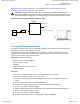
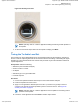
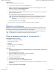
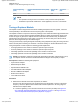
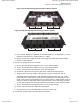
Table Of Contents
- Exhibit D - Tune-Up Procedure-User Manual-front
- Pages from MN003557A01-AL_enus_SLR1000_Repeater_Basic_Service_and_Installation_Manual_NAG
- Pages from Exhibit D - Tune-Up Procedure-User Manual-d2header
- MN003581A01_AA_enus_MOTOTRBO_SLR_1000_Repeater_Quick_Start_Guide-modified

Figure 23: SLR 1000 UHF Repeater Band Reject (Notch) Duplexer
Tuning Screws - High Tuning Screws - Low
Figure 24: SLR 1000 VHF Repeater Band Reject (Notch) Duplexer
Tuning Screws - Low
Tuning Screws - High
a On the network analyzer (or equivalent) set the start frequency to a LOW frequency – 3 MHz,
and set the stop frequency to a HIGH frequency + 3 MHz.
b Using the sweep menu, adjust the power out to as high as possible, presumably 10 dBm.
c Perform a 2-port calibration.
2 View the s11 log mag return loss, as follows:
a Connect the LOW port on the duplexer to port 1 on the network analyzer.
b Connect the ANT port on the duplexer to port 2 on the network analyzer.
c Connect a 50 ohm load to the HIGH port on the network analyzer.
d Set marker 1 (M1) as the low frequency and marker 2 (M2) as the high frequency.
e Using the three T10 tuning screws on the LOW side, tune M1 for best return loss, s11.
The results should be better than -12 dB. The lower the number is best (such as, -20 dB
is preferable than -10 dB). Shorter screws (turned clockwise) are for a lower frequency and
longer screws (turned counterclockwise) are for a higher frequency. Keep all three screws for
each port at about the same depth when tuning each section. Later in this tuning procedure,
you may notice that the three LOW port screws are shorter than the three HIGH port screws.
f Connect the HIGH port on the duplexer to port 1 on the network analyzer.
g Connect a 50 ohm load to the LOW side on the duplexer.
h Tune the three screws on the HIGH side for a best return loss on M2.
3 View the s21 log mag insertion loss and rejection, as follows:
MN003557A01-AL
Chapter 8 : SLR 1000 Programming and Tuning
71
Applicant: Motorola Solutions
Equipment Type: ABZ99FT3096B / 109AB-99FT3096B
Tune-Up Procedure
Exhibit D1 8 of 11