APPLICANT: MOTOROLA SOLUTIONS EQUIPMENT TYPE: ABZ99FT3096B 109AB-99FT3096B User Information User Information Tune-up and user / operational manual information are provided in the following exhibits.
APPLICANT: MOTOROLA SOLUTIONS EQUIPMENT TYPE: ABZ99FT3096B 109AB-99FT3096B Tune-Up Procedure Tune-Up Procedure A procedure to ensure that the device is tuned to the correct frequency / frequency range and that it is operating at the proper level. This exhibit is only required for licensed transmitters. Content from Chapter 8 of the document “MOTOTRBO™ SLR 1000 Repeater Basic Service and Installation Manual” (part number MN003557A01-AL, June 2022) is included in the following pages.
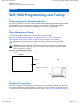
Applicant: Motorola Solutions Equipment Type: ABZ99FT3096B / 109AB-99FT3096B MN003557A01-AL Chapter 8 : SLR 1000 Programming and Tuning Chapter 8 SLR 1000 Programming and Tuning 8.1 Programming and Tuning Introduction This section provides an overview of the MOTOTRBO Radio Management (RM) and the MOTOTRBO Tuner application for use on Windows 7, Windows 8, or Windows 8.1. These two MOTOTRBO applications are used for the configuration and alignment of the SLR 1000 Repeater . 8.
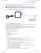
Applicant: Motorola Solutions Equipment Type: ABZ99FT3096B / 109AB-99FT3096B MN003557A01-AL Chapter 8 : SLR 1000 Programming and Tuning Equipment Setup on page 65 and Figure 11: SLR 1000 Repeater Transceiver Board Connector Locations on page 45 for the connectors on the repeater. CAUTION: The high-speed solid-state antenna switch is only operable in Extended Range Direct Mode (ERDM) mode.
Applicant: Motorola Solutions Equipment Type: ABZ99FT3096B / 109AB-99FT3096B MN003557A01-AL Chapter 8 : SLR 1000 Programming and Tuning 8.5 Tuning the Rx Audio Level Set The procedure outlined in this section is used to set the receive output audio level from the repeater for a given RF deviation of the received RF signal. Perform this procedure any time the Rx audio level requires adjustment.
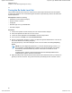
Applicant: Motorola Solutions Equipment Type: ABZ99FT3096B / 109AB-99FT3096B MN003557A01-AL Chapter 8 : SLR 1000 Programming and Tuning Figure 22: Auxiliary Connector NOTE: Optimally, load Pin 7 with the application loading used during normal operation of the repeater. 7 To save the new tuned softpot value into the repeater codeplug, click Write. 8.6 Tuning the Tx Audio Level Set This procedure is used to allow adjustment of the transmitter audio level the repeater is expecting at the Aux connector.
Applicant: Motorola Solutions Equipment Type: ABZ99FT3096B / 109AB-99FT3096B MN003557A01-AL Chapter 8 : SLR 1000 Programming and Tuning 5 In the tree view, select TX, then select Tx Audio Level. 6 Enter the tuning frequency into the Communication Analyzer (the value displayed in the Tuner application under the heading Frequency Points. 7 To key up the repeater, click PTT Toggle.
Applicant: Motorola Solutions Equipment Type: ABZ99FT3096B / 109AB-99FT3096B MN003557A01-AL Chapter 8 : SLR 1000 Programming and Tuning 9 Adjust the softpot value until the maximum deviation is 92% of the rated system deviation (RSD). This adjustment is tested in a 12.5 kHz channel spacing, so 92% of 2.5 kHz is 2.3 kHz. 10 Set the modulation limit to 92% so that any additional deviation incurred by the transmitter VCOs over temperature is compensated for.
Applicant: Motorola Solutions Equipment Type: ABZ99FT3096B / 109AB-99FT3096B MN003557A01-AL Chapter 8 : SLR 1000 Programming and Tuning Channel Spacing (kHz) Relative Standard Deviation (RSD) (kHz) 92% of RS (kHz) Tolerance (Hz) 25.0 5.0 4.6 +0/-100 NOTE: • The repeater is factory-tuned in accordance to this procedure and specification. • Verification is performed outside of the Tuner application, such as in normal mode. 8.8 Tuning a Duplexer Module The duplexer module is shipped untuned.
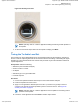
Applicant: Motorola Solutions Equipment Type: ABZ99FT3096B / 109AB-99FT3096B MN003557A01-AL Chapter 8 : SLR 1000 Programming and Tuning Figure 23: SLR 1000 UHF Repeater Band Reject (Notch) Duplexer Tuning Screws - High Tuning Screws - Low Figure 24: SLR 1000 VHF Repeater Band Reject (Notch) Duplexer Tuning Screws - High Tuning Screws - Low a On the network analyzer (or equivalent) set the start frequency to a LOW frequency – 3 MHz, and set the stop frequency to a HIGH frequency + 3 MHz.
Applicant: Motorola Solutions Equipment Type: ABZ99FT3096B / 109AB-99FT3096B MN003557A01-AL Chapter 8 : SLR 1000 Programming and Tuning The goal is to keep M2 better than -1.7 dB (for example, -1.3 dB) and M1 less than -65 dB (for example, -67 dB). See Figure 25: Example for HIGH Port Tuning of the UHF Duplexer on page 72.
Applicant: Motorola Solutions Equipment Type: ABZ99FT3096B / 109AB-99FT3096B MN003557A01-AL Chapter 8 : SLR 1000 Programming and Tuning Figure 26: Example for LOW Port Tuning of the UHF Duplexer d Using the three T10 tuning screws on the HIGH side, tune M1 for best insertion loss, s21, while keeping the isolation (M2) better than 65 dB. The results should be better than -1.7 dB.
Applicant: Motorola Solutions Equipment Type: ABZ99FT3096B / 109AB-99FT3096B MN003557A01-AL Chapter 8 : SLR 1000 Programming and Tuning Figure 27: Rejection of Each Port for UHF Duplexer 5 Complete the tuning procedure, as follows: a If the results are similar to Figure 27: Rejection of Each Port for UHF Duplexer on page 74 with better than -65 dB isolation between the LOW and HIGH ports of the duplexer, carefully tighten the nuts on the six T10 torque screws.
APPLICANT: MOTOROLA SOLUTIONS EQUIPMENT TYPE: ABZ99FT3096B 109AB-99FT3096B User / Operational Manual Operational or User’s Manual The manual should include instruction, installation, operator, or technical manuals with required ‘information to the users’. This manual should include a statement that cautions the user that changes or modifications not expressly approved by the party responsible for compliance could void the user’s authority to operate the equipment.
Applicant: Motorola Solutions Equipment Type: ABZ99FT3096B / 109AB-99FT3096B PROFESSIONAL DIGITAL TWO-WAY RADIO MOTOTRBO™ SLR 1000 Repeater QUICK START GUIDE en-US fr-CA Exhibit D2 1 of 14
Applicant: Motorola Solutions Equipment Type: ABZ99FT3096B / 109AB-99FT3096B Exhibit D2 2 of 14
Applicant: Motorola Solutions Equipment Type: ABZ99FT3096B / 109AB-99FT3096B MOTOTRBO™ SLR 1000 Repeater Quick Start Guide Notations Used in This Manual Note and caution notations are used throughout the text in this publication. These notations are used to emphasize that safety hazards exist, and due care must be taken and observed. ! CAUTION indicates a potentially hazardous situation which, if not avoided, might result in equipment damage.
Applicant: Motorola Solutions Equipment Type: ABZ99FT3096B / 109AB-99FT3096B General Safety and Installation Standards and Guidelines WARNING WARNING: For safe installation, operation, service and repair of this equipment, follow the safety precautions and instructions described below, as well as any additional safety information in Motorola’s product service and installation manuals and the Motorola R56 Standards and Guidelines for Communications Sites manual.
Applicant: Motorola Solutions • • • • • • Equipment Type: ABZ99FT3096B / 109AB-99FT3096B restrictions applied to the location and about any precautions that shall be taken; and access is through the use of a tool or lock and key, or other means of security, and is controlled by the authority responsible for the location.” Ensure that the installation area can safely support the weight on the repeater. Burn hazard. The metal housing of the product may become extremely hot.
Applicant: Motorola Solutions Refer to product specific manuals for detailed safety and installation instructions. Manuals can be obtained with product orders, downloaded from https://businessonline.motorolasolutions.com or purchased through the Motorola Aftermarket & Accessory Department. This is a class A product. In a domestic environment, this product may cause radio interference in which case the user may be required to take adequate measures.
Applicant: Motorola Solutions Environmental Conditions at Intended Installation Site The SLR 1000 Repeater is a rugged, compact repeater suited for indoor and outdoor locations where moisture and dust may be common. The repeater may be installed in any suitable location meeting the restricted access criteria and not exceeding the equipment specifications for temperature and environmental exposure (ingress). Equipment Type: ABZ99FT3096B / 109AB-99FT3096B Procedure: 1.
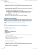
Applicant: Motorola Solutions Equipment Type: ABZ99FT3096B / 109AB-99FT3096B 2. From the mounting hardware, insert the four M6 screws into the repeater chassis side fins and partially tighten. See Figure 2. Figure 3. Bracket Receiving Slots Figure 2: Location of M6 Screw Mounts 3. Place the repeater chassis into the bracket by sliding the M6 screws into the receiving slots on the bracket. Torque to 60 in-lbs. See Figure 3.
Applicant: Motorola Solutions Equipment Type: ABZ99FT3096B / 109AB-99FT3096B Figure 5: U-Bolt and Pole Mount Bracket Assembly Figure 4: U-Bolt and Pole Mount Bracket Assembly d. Tighten the inner nuts against the pole mount bracket and torque to 300 in/lb. 2. If using the band clamps for installation, perform the following actions: a. Slide the band clamps through the slots on the pole mount bracket and attach the bracket to the pole. See Figure 6. b.
Applicant: Motorola Solutions Equipment Type: ABZ99FT3096B / 109AB-99FT3096B Power Input Requirements After the repeater equipment has been mechanically installed, electrical connections must be made. This involves making the following connections to: • When applicable, AC input power cabling: 100–240 Volts (47–63 Hz) at 1 A maximum. • When applicable, DC input power cabling: 10.8 VDC to 15.6 VDC at 4 A maximum. Note: AC power supply accessories must be ordered separately.
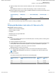
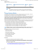
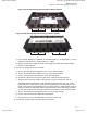
Applicant: Motorola Solutions NOTE: Equipment Type: ABZ99FT3096B / 109AB-99FT3096B Follow all applicable electrical codes for the end use country and locality. Connections Table 1: Connector Type and Primary Function 12 Figure 9 illustrates the position of the connectors located on the repeater. Table 1 identifies the connector types as well as the primary function of the connector. 13 Table 1: Connector Type and Primary Function 15 NO Connector 1 2 3 4 N-Type – Female 5 6 7 M6 TORX Screw 2.
Applicant: Motorola Solutions Equipment Type: ABZ99FT3096B / 109AB-99FT3096B 1 15 2 14 3 13 4 12 5 11 6 8 10 9 7 Figure 9: SLR 1000 Repeater Connections 10 English English Exhibit D2 12 of 14
Applicant: Motorola Solutions Post-Installation Checklist Applying Power After the SLR 1000 Repeater has been mechanically installed and all electrical connections have been made, power may now be applied and the repeater checked for proper operation.
Applicant: Motorola Solutions Equipment Type: ABZ99FT3096B / 109AB-99FT3096B MOTOROLA, MOTO, MOTOROLA SOLUTIONS and the Stylized M logo are trademarks or registered trademark of Motorola Trademark Holdings, LLC and are used under license. All other trademarks are the property of their respective owners. © 2017 Motorola Solutions, Inc. All rights reserved.