
User's Manual

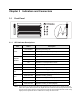
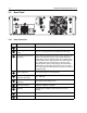

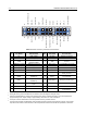
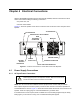
Table Of Contents
- Product Safety and RF Exposure Compliance
- Manual Revisions
- Parts Ordering
- Computer Software Copyrights
- Document Copyrights
- Disclaimer
- Trademarks
- Table of Contents
- List of Figures
- Related Publications
- Repeater Model Numbering Scheme
- Commercial Warranty
- Chapter 1 Pre-Installation Considerations
- Chapter 2 Mechanical Installation
- Chapter 3 Indicators and Connectors
- Chapter 4 Electrical Connections
- Chapter 5 Post-Installation Checklist
- Chapter 6 Accessories
- Appendix A Replacement Parts Ordering
- Appendix B Motorola Service Centers

Chapter 3 Indicators and Connectors
3.1 Front Panel
3.1.1 LED Indicator Descriptions
NOTE: When repeater is in Dynamic Mixed Mode, both Digital and Analog LEDs are used to indicate the dynamic
status of the repeater. When repeater is idle, Digital LED status is solid BLUE and Analog LED status is solid
YELLOW. During Analog operation, Analog LED status is solid YELLOW and Digital LED status is OFF. During
digital operation, Digital LED status is solid BLUE and Analog LED status is OFF.
LED Status Description
Power
Solid GREEN Repeater powered by AC.
Solid RED Repeater powered by backup battery.
Off Repeater powered off.
Repeater
Disabled
Solid RED Repeater function disabled.
Blinking RED Repeater in self-test mode.
Off Repeater in normal operational mode.
Digital Solid BLUE Repeater in Digital Mode.
Analog Solid YELLOW Repeater in Analog Mode.
Tx-A
Solid GREEN Repeater transmitting (Analog).
Solid GREEN Repeater transmitting on Slot A (Digital).
Rx-A
Solid YELLOW Repeater receiving (Analog).
Solid YELLOW Repeater receiving on Slot A (Digital).
Tx-B Solid GREEN Repeater transmitting on Slot B (Digital).
Rx-B Solid YELLOW Repeater receiving on Slot B (Digital).