
Installation Manual

6 6880101W80-C June, 2002
Mobile 1/4-Wave Antennas Installation
NOTE
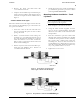
The coaxial cable will normally not be
harmed by opening and closing the
trunk, although reasonable care should
be exercised. The rubber molding around
the trunk lid will prevent damage to the
cable.
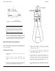
5. Route the cable from the mounting base to the
radio set. Rubber grommets should be used in
any sheet metal holes through which the cable
is routed. Ensure that the cable will not be
pinched during normal vehicle operation.
Mini-UHF Connector Installation
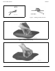
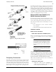
Use Motorola hand tool part #66-80388A26 (Refer to
Figure 12). A deluxe rachet type tool is available; order
part #66-80334B40.
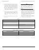
Installation Instructions
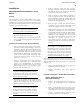
1. Slip ferrule and collar onto cable. Refer to
Figure 13.
2. Prepare cable to strip dimensions per
Figure 14, which is also marked on the hand
tool.
3. Insert stripped cable into plug body until con-
ductor is exposed (front end) and dielectric
bottoms inside body. Refer to Figure 13.
4. Crimp center contact using proper crimp
section of tool. Refer to Figure 12 marked
"CENTER CONTACT."
5. Push collar forward onto plug assembly. Fit
cable braid over the support sleeve of the con-
nector. Refer to Figure 13.
6. Push ferrule over braid until flange butts
against connector body. Refer to Figure 13.
Using the correct crimp area of the tool, crimp
the ferrule close to the plug body. See
Figure 12, crimp location "C." Crimp ferrule a
second time close to the cable end.
7. The protruding center conductor should be
trimmed flush with the end of the center con-
tact.
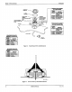
Figure 11. Typical Mount Location
Figure 12.