
User's Manual


English
English
10
Front Panel LEDs
After turning on the repeater power, the seven LEDs on the repeater
front panel:
1. Light for approximately one second to indicate that they are
functional, then
2. Go off for one second.
3. Indicate the operational status of the repeater.
Front Panel Speaker/Microphone
• Microphone Connector (RJ45) Jack: accepts interface with the
GMMN4063_ microphone accessory.
• Volume Increase Button: Raises the volume level of the
integrated front panel speaker.
• Volume Decrease/Mute Button: Lowers/Mutes the volume level
of the integrated front panel speaker.
Verifying Proper Operation
Operation of the repeater can be verified by:
• Observing the state of the seven LEDs located on the front panel,
and
• Exercising radio operation.
Archiving
Copying the Base Station Repeater Codeplug Data to a
Computer
Proceed to the Customer Programming Software (CPS) configuration
procedures to customize the repeater parameters (e.g., operating
frequency, PL, codes, etc.). Backup the codeplug data of the SLR
8000 Series Base Station Repeater using the CPS application.
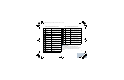
The SLR 8000 Series Base Station Repeater connector to facilitate
the CPS configuration is a USB Type-B host connection located on
the front of the repeater. See Figure 4.
Figure 4: Front panel
Motorola Service Center
To find out more about Motorola Service Centers, please visit
http://www.motorolasolutions.com
Some repeater components can become extremely
hot during operation. Turn off all power to the
repeater and wait until sufficiently cool before
touching the repeater.
USB service port
Microphone
Connector port
Volume
Increase Button
Volume
Decrease/Mute
Button
SLR_8000_NAG.book Page 10 Tuesday, November 17, 2015 11:38 PM