
User's Manual


7
English
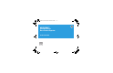
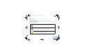
See Figure 2a and Figure 2b for an illustration of the mounting
hardware configured for a cabinet installation.
Power Input Requirements
After the repeater equipment has been mechanically installed,
electrical connections must be made. This involves making the
following connections to:
• When applicable, AC input power cabling: 100–240 Volts
(47–63Hz) at 10A maximum.
• When applicable, DC input power cabling: 11–15.5 VDC at 23A
maximum, or 20.6 - 32 VDC at 23A maximum.
Grounding
Connect a bonding wire from the repeaters ground screw to the site
ground point. The size of the bonding wire used for this connection
must be 6 AWG minimum.
NOTE: Follow all applicable electrical codes for the end use
country and locality.
Cable Connections
• Connect RF coaxial cables to transmit (N-Type Female) and
receive (BNC Female) antenna connectors.
• System cable connections are made through the Aux and/or
Ethernet connectors.
Do not apply AC power to the repeater at this time. Make
sure that the circuit breaker associated with the AC outlet
is turned off.
The AC socket-outlet must be installed near the
equipment and must be easily accessible.
Ensure that the appropriate voltage is connected with a
nominal 13.6VDC (11–15.5 VDC), or nominal 27.2 VDC
(20.6 - 32 VDC)
Figure 2a: Mounting hardware
Figure 2b: Mounting hardware
W A R N I N G
The base station/repeater is to be connected to a battery
supply that is in accordance with the applicable electrical
codes for the end use country; for example, the National
Electric Code ANSI/NFPA No.70 for the U.S.
Refer to Motorola Quality Standards Fixed Network
Equipment Installation manual, R56 for complete
information regarding lightning protection.
SLR_8000_NAG.book Page 7 Tuesday, November 17, 2015 11:38 PM