
Installation Manual
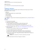
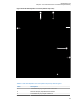
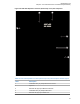

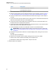
Table Of Contents
- Foreword
- General Safety and Installation Standards and Guidelines
- Declaration of Conformity
- MOTOTRBO SLR 1000 Repeater Supplemental Safety and Installation Requirements
- Environmental Information
- Document History
- Contents
- List of Figures
- List of Tables
- List of Procedures
- Related Publications
- Summary of Bands Available
- Commercial Warranty
- SLR 1000 Repeater
- SLR 1000 Satellite Receiver
- SLR 1000 Transceiver Board
- SLR 1000 Front Panel
- SLR 1000 Bottom Panel
- SLR 1000 Test Equipment And Service Aids
- SLR 1000 Performance Check or Testing
- SLR 1000 Programming and Tuning
- SLR 1000 Maintenance and Disassembly/Reassembly
- SLR 1000 Installation
- 10.1 Pre-Installation Considerations
- 10.2 SLR 1000 Repeater Package Contents
- 10.3 Mounting the SLR 1000 Repeater to a Wall or Ceiling
- 10.4 Mounting the SLR 1000 Repeater to a Pole
- 10.5 Electrical Connections
- 10.6 General Bonding and Grounding Requirements
- 10.7 General Cabling Requirements
- 10.8 Post Installation Checklist
- Appendix A: Accessories
- Appendix B: Replacement Parts Ordering
- Appendix C: Motorola Solutions Service Centers
- Appendix D: SLR 1000 Series Third-Party Controllers
- Appendix E: MOTOTRBO Repeater EME Assessment
- Glossary of Terms and Acronyms
- Alert tone
- Analog
- ASIC
- AUX
- Band
- CTCSS
- Clear
- Conventional
- CPS
- Default
- Digital
- DPL
- DSP
- EIA
- ESD
- EU
- FCC
- FM
- Frequency
- FRU
- FSK
- GNSS
- GPIO
- IC
- IF
- I/O
- kHz
- LCD
- LED
- MDC
- MHz
- MISO
- MOSI
- PA
- PC Board
- PFC
- PL
- Programming Cable
- PTT
- Radio Management
- Receiver
- Repeater
- RF
- RSSI
- Rx
- SCM
- SELV
- Signal
- SINAD
- SLR
- Spectrum
- SPI
- Squelch
- TOT
- TPL
- Transceiver
- Transmitter
- Trunking
- Tx
- UHF
- USB
- VCO
- VCTCXO
- VHF
- VIP
- VSWR
- WLAN

Label Description
4 Receiver RF (Rx) Input Cable Port
5 Front Panel Flex Connector
4 Install the antenna switch into the repeater, as follows:
a Place the antenna switch into the chassis and align the screw openings, as shown in Figure
31: SLR 1000 Repeater Front View (without top cover) with an Antenna Switch
on page 91.
b Secure the antenna switch to the chassis with the two M3 screws using a T10 bit. Torque to
13 in.-lbs.
c Connect one end of the power cable into the P1000 connector on the antenna switch and the
other end to the header connector on the repeater board.
d Connect one end of an MCX cable into the J1000/TX connector on the antenna switch and
the other end to the Tx output board connection.
e Connect one end of the other MCX cable into the J1001/RX connector on the antenna switch
and the other end to the Rx input board connection.
f Connect the Station Rx cable to the J1002/ANT connector on the antenna switch.
IMPORTANT: Ensure that the antenna cable is routed away from the Tx cable. See
Figure 31: SLR 1000 Repeater Front View (without top cover) with an Antenna Switch
on page
91.
g Reattach the front panel flex cable to the front panel display board, making sure not to bend
the cable.
The cable stops at the black line.
h Place the top cover back onto the chassis, making sure not to pinch any cables.
i Hold the cover onto the chassis and carefully turn the repeater over.
j Reinstall the four M4 screws using a T20 bit. Torque to 26 in.-lbs.
5 Restore power to the repeater.
MN003557A01-AF
Chapter 9: SLR 1000 Maintenance and Disassembly/Reassembly
90