
Installation Manual
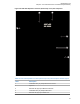

Table Of Contents
- Foreword
- General Safety and Installation Standards and Guidelines
- Declaration of Conformity
- MOTOTRBO SLR 1000 Repeater Supplemental Safety and Installation Requirements
- Environmental Information
- Document History
- Contents
- List of Figures
- List of Tables
- List of Procedures
- Related Publications
- Summary of Bands Available
- Commercial Warranty
- SLR 1000 Repeater
- SLR 1000 Satellite Receiver
- SLR 1000 Transceiver Board
- SLR 1000 Front Panel
- SLR 1000 Bottom Panel
- SLR 1000 Test Equipment And Service Aids
- SLR 1000 Performance Check or Testing
- SLR 1000 Programming and Tuning
- SLR 1000 Maintenance and Disassembly/Reassembly
- SLR 1000 Installation
- 10.1 Pre-Installation Considerations
- 10.2 SLR 1000 Repeater Package Contents
- 10.3 Mounting the SLR 1000 Repeater to a Wall or Ceiling
- 10.4 Mounting the SLR 1000 Repeater to a Pole
- 10.5 Electrical Connections
- 10.6 General Bonding and Grounding Requirements
- 10.7 General Cabling Requirements
- 10.8 Post Installation Checklist
- Appendix A: Accessories
- Appendix B: Replacement Parts Ordering
- Appendix C: Motorola Solutions Service Centers
- Appendix D: SLR 1000 Series Third-Party Controllers
- Appendix E: MOTOTRBO Repeater EME Assessment
- Glossary of Terms and Acronyms
- Alert tone
- Analog
- ASIC
- AUX
- Band
- CTCSS
- Clear
- Conventional
- CPS
- Default
- Digital
- DPL
- DSP
- EIA
- ESD
- EU
- FCC
- FM
- Frequency
- FRU
- FSK
- GNSS
- GPIO
- IC
- IF
- I/O
- kHz
- LCD
- LED
- MDC
- MHz
- MISO
- MOSI
- PA
- PC Board
- PFC
- PL
- Programming Cable
- PTT
- Radio Management
- Receiver
- Repeater
- RF
- RSSI
- Rx
- SCM
- SELV
- Signal
- SINAD
- SLR
- Spectrum
- SPI
- Squelch
- TOT
- TPL
- Transceiver
- Transmitter
- Trunking
- Tx
- UHF
- USB
- VCO
- VCTCXO
- VHF
- VIP
- VSWR
- WLAN

Label Description
6 Front Panel Flex Connector
Return to Process
SLR 1000 Maintenance and Disassembly/Reassembly
on page 82
9.5
Installing a High-Speed Solid-State Antenna Switch
The high-speed solid-state antenna switch is required for a single antenna, single frequency operation.
With the use of the antenna switch, the SLR 1000 Repeater can be configured as a Direct Mode
Range Extender for use with the Extended Range Direct Mode feature. Alternatively, two separate
antennas may be used for RX and TX operation, but a minimum of 40 dB isolation between the two
antennas must be maintained.
CAUTION: The high-speed solid-state antenna switch is only operable in Extended Range
Direct Mode (ERDM) mode and should not be installed in the repeater if all the channels are not
enabled as Extended Range Direct Mode. Operating in any mode other than ERDM, may cause
damage to the antenna switch board.
Prerequisites: Obtain the following:
•
Contents of the antenna switch package. Consists of:
- One antenna switch
- Two M3 screws
- Two Micro Coaxial (MCX) cables
- One power cable
• T10 bit screwdriver
• T20 bit screwdriver
Procedure:
1 Turn off power to the repeater.
2 Disassemble the repeater, as follows:
a Turn the repeater over and remove the four M4 screws using a T20 bit.
b Hold the cover onto the chassis and carefully turn the repeater over.
c Slowly remove the top cover, making sure not to damage the front panel flex cable.
3 Disconnect the following cables. See Figure 30: SLR 1000 Repeater Front View (without top
cover) on page 89.
a Disconnect the front panel flex cable from the front panel display board.
b Cut the tie wrap that secures the Tx and Rx cables.
c Disconnect the Rx cable from the Rx board connection by gently pulling up.
d Disconnect the Tx cable from the Tx board connection by gently pulling up.
e Remove the Tx cable by either cutting the cable from the Tx input port or tie wrapping the
cable.
CAUTION: The Tx cable must not touch any components on the board.
MN003557A01-AF
Chapter
9: SLR 1000 Maintenance and Disassembly/Reassembly
88