
Installation Manual
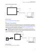
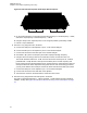
Table Of Contents
- Foreword
- General Safety and Installation Standards and Guidelines
- Declaration of Conformity
- MOTOTRBO SLR 1000 Repeater Supplemental Safety and Installation Requirements
- Environmental Information
- Document History
- Contents
- List of Figures
- List of Tables
- List of Procedures
- Related Publications
- Summary of Bands Available
- Commercial Warranty
- SLR 1000 Repeater
- SLR 1000 Satellite Receiver
- SLR 1000 Transceiver Board
- SLR 1000 Front Panel
- SLR 1000 Bottom Panel
- SLR 1000 Test Equipment And Service Aids
- SLR 1000 Performance Check or Testing
- SLR 1000 Programming and Tuning
- SLR 1000 Maintenance and Disassembly/Reassembly
- SLR 1000 Installation
- 10.1 Pre-Installation Considerations
- 10.2 SLR 1000 Repeater Package Contents
- 10.3 Mounting the SLR 1000 Repeater to a Wall or Ceiling
- 10.4 Mounting the SLR 1000 Repeater to a Pole
- 10.5 Electrical Connections
- 10.6 General Bonding and Grounding Requirements
- 10.7 General Cabling Requirements
- 10.8 Post Installation Checklist
- Appendix A: Accessories
- Appendix B: Replacement Parts Ordering
- Appendix C: Motorola Solutions Service Centers
- Appendix D: SLR 1000 Series Third-Party Controllers
- Appendix E: MOTOTRBO Repeater EME Assessment
- Glossary of Terms and Acronyms
- Alert tone
- Analog
- ASIC
- AUX
- Band
- CTCSS
- Clear
- Conventional
- CPS
- Default
- Digital
- DPL
- DSP
- EIA
- ESD
- EU
- FCC
- FM
- Frequency
- FRU
- FSK
- GNSS
- GPIO
- IC
- IF
- I/O
- kHz
- LCD
- LED
- MDC
- MHz
- MISO
- MOSI
- PA
- PC Board
- PFC
- PL
- Programming Cable
- PTT
- Radio Management
- Receiver
- Repeater
- RF
- RSSI
- Rx
- SCM
- SELV
- Signal
- SINAD
- SLR
- Spectrum
- SPI
- Squelch
- TOT
- TPL
- Transceiver
- Transmitter
- Trunking
- Tx
- UHF
- USB
- VCO
- VCTCXO
- VHF
- VIP
- VSWR
- WLAN

transmit signal and rejects the receive signal. Concurrently, the receive cavity set must be tuned to
pass the receive signal and reject the transmit signal.
Tuning is performed by injecting RF signals and making tuning adjustments (using the tuning rods and
trimmer screws) while monitoring for maximum or minimum readings on the RF millivoltmeter. Field
tuning the duplexer module requires the following general adjustments:
•
Tune high-pass/low-notch cavities for maximum pass and reject response
• Tune low-pass/high-notch cavities for maximum pass and reject response
• Check high-pass/low-notch and low-pass/high-notch cavities for insertion loss
• Check high-pass/low-notch and low-pass/high-notch cavities for isolation
NOTICE: If the duplexer module is tuned and the specifications are within a large margin of
error, the duplexer must be returned to the Motorola Solutions Support Center (SSC) for repair.
Prerequisites: Obtain the following test equipment:
•
2-port network analyzer
• Network analyzer cables
• Open/short/load calibration kit
• Two SMA female to MCX adapters
• N-male to SME female adapter
• Small crescent wrench
• T10 TORX bit and driver
Procedure:
1 Determine the transmit and receive frequencies, as follows:
The less of the two frequencies is the LOW frequency and the greater of the two is the HIGH
frequency. Choose a duplexer that includes both of these frequencies in its tuning range as
indicated on the duplexer label.
a Loosen the tightening nut on the three cavities for each section (six total). See Figure 23:
SLR 1000 UHF Repeater Band Reject (Notch) Duplexer on page 77 and Figure 24: SLR
1000 VHF Repeater Band Reject (Notch) Duplexer on page 78
Figure 23: SLR 1000 UHF Repeater Band Reject (Notch) Duplexer
Tuning Screws - High Tuning Screws - Low
MN003557A01-AF
Chapter 8: SLR 1000 Programming and Tuning
77