
Installation Manual
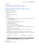
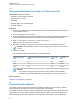
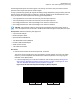
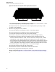
Table Of Contents
- Foreword
- General Safety and Installation Standards and Guidelines
- Declaration of Conformity
- MOTOTRBO SLR 1000 Repeater Supplemental Safety and Installation Requirements
- Environmental Information
- Document History
- Contents
- List of Figures
- List of Tables
- List of Procedures
- Related Publications
- Summary of Bands Available
- Commercial Warranty
- SLR 1000 Repeater
- SLR 1000 Satellite Receiver
- SLR 1000 Transceiver Board
- SLR 1000 Front Panel
- SLR 1000 Bottom Panel
- SLR 1000 Test Equipment And Service Aids
- SLR 1000 Performance Check or Testing
- SLR 1000 Programming and Tuning
- SLR 1000 Maintenance and Disassembly/Reassembly
- SLR 1000 Installation
- 10.1 Pre-Installation Considerations
- 10.2 SLR 1000 Repeater Package Contents
- 10.3 Mounting the SLR 1000 Repeater to a Wall or Ceiling
- 10.4 Mounting the SLR 1000 Repeater to a Pole
- 10.5 Electrical Connections
- 10.6 General Bonding and Grounding Requirements
- 10.7 General Cabling Requirements
- 10.8 Post Installation Checklist
- Appendix A: Accessories
- Appendix B: Replacement Parts Ordering
- Appendix C: Motorola Solutions Service Centers
- Appendix D: SLR 1000 Series Third-Party Controllers
- Appendix E: MOTOTRBO Repeater EME Assessment
- Glossary of Terms and Acronyms
- Alert tone
- Analog
- ASIC
- AUX
- Band
- CTCSS
- Clear
- Conventional
- CPS
- Default
- Digital
- DPL
- DSP
- EIA
- ESD
- EU
- FCC
- FM
- Frequency
- FRU
- FSK
- GNSS
- GPIO
- IC
- IF
- I/O
- kHz
- LCD
- LED
- MDC
- MHz
- MISO
- MOSI
- PA
- PC Board
- PFC
- PL
- Programming Cable
- PTT
- Radio Management
- Receiver
- Repeater
- RF
- RSSI
- Rx
- SCM
- SELV
- Signal
- SINAD
- SLR
- Spectrum
- SPI
- Squelch
- TOT
- TPL
- Transceiver
- Transmitter
- Trunking
- Tx
- UHF
- USB
- VCO
- VCTCXO
- VHF
- VIP
- VSWR
- WLAN

8.7.2
Verifying the Modulation Limit (with no Tx Data and no PL)
Prerequisites: Obtain the following:
•
Wattmeter (Communication Analyzer)
• Service monitor or counter
• 20 dB pad
• Standard Type A to Type B USB cable
• Personal computer
Procedure:
1 Connect the repeater antenna port to the attenuation pad, if necessary, before connecting to the
Communication Analyzer.
2 Power the repeater from a DC source.
3 In Radio Management (RM), program the repeater with any frequency within the specified range
of the repeater under test, and set the repeater for low power and disable the repeat path.
4 Apply a 1 kHz signal at 1.2 Vrms to Pin 1 of the Aux connector.
Signal ground is Pin 4 of the Aux connector.
5 Key up the repeater by grounding Pin 2 of the Aux connector and measuring the deviation
NOTICE: Radio Management
must have Pin 2 configured as an active low with the PTT
function.
6 De-key the repeater.
The deviation should meet the limits shown in the following table.
Channel Spacing
(kHz)
Relative Standard Deviation (RSD)
(kHz)
92% of RS
(kHz)
Tolerance
(Hz)
12.5 2.5 2.3 +0/-50
20.0 4.0 3.68 +0/-80
25.0 5.0 4.6 +0/-100
NOTICE:
•
The repeater is factory-tuned in accordance to this procedure and specification.
• Verification is performed outside of the Tuner application, such as in normal mode.
Return to Process
Modulation Limit Alignment on page 74
8.8
Tuning a Duplexer Module
The duplexer module is shipped untuned. Before installing the duplexer into the repeater, it must be
tuned specifically to the transmit and receive frequency pairs of the repeater.
The duplexer module is composed of three low-pass/high-notch cavities and three high-pass/low-notch
cavities. Each set of three cavities provides bandpass filtering for either the transmit RF signal or the
receive RF signal. In general, the duplexer must be tuned so that the transmit cavity set passes the
MN003557A01-AF
Chapter
8: SLR 1000 Programming and Tuning
76