
Installation Manual
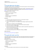
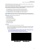
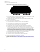
Table Of Contents
- Foreword
- General Safety and Installation Standards and Guidelines
- Declaration of Conformity
- MOTOTRBO SLR 1000 Repeater Supplemental Safety and Installation Requirements
- Environmental Information
- Document History
- Contents
- List of Figures
- List of Tables
- List of Procedures
- Related Publications
- Summary of Bands Available
- Commercial Warranty
- SLR 1000 Repeater
- SLR 1000 Satellite Receiver
- SLR 1000 Transceiver Board
- SLR 1000 Front Panel
- SLR 1000 Bottom Panel
- SLR 1000 Test Equipment And Service Aids
- SLR 1000 Performance Check or Testing
- SLR 1000 Programming and Tuning
- SLR 1000 Maintenance and Disassembly/Reassembly
- SLR 1000 Installation
- 10.1 Pre-Installation Considerations
- 10.2 SLR 1000 Repeater Package Contents
- 10.3 Mounting the SLR 1000 Repeater to a Wall or Ceiling
- 10.4 Mounting the SLR 1000 Repeater to a Pole
- 10.5 Electrical Connections
- 10.6 General Bonding and Grounding Requirements
- 10.7 General Cabling Requirements
- 10.8 Post Installation Checklist
- Appendix A: Accessories
- Appendix B: Replacement Parts Ordering
- Appendix C: Motorola Solutions Service Centers
- Appendix D: SLR 1000 Series Third-Party Controllers
- Appendix E: MOTOTRBO Repeater EME Assessment
- Glossary of Terms and Acronyms
- Alert tone
- Analog
- ASIC
- AUX
- Band
- CTCSS
- Clear
- Conventional
- CPS
- Default
- Digital
- DPL
- DSP
- EIA
- ESD
- EU
- FCC
- FM
- Frequency
- FRU
- FSK
- GNSS
- GPIO
- IC
- IF
- I/O
- kHz
- LCD
- LED
- MDC
- MHz
- MISO
- MOSI
- PA
- PC Board
- PFC
- PL
- Programming Cable
- PTT
- Radio Management
- Receiver
- Repeater
- RF
- RSSI
- Rx
- SCM
- SELV
- Signal
- SINAD
- SLR
- Spectrum
- SPI
- Squelch
- TOT
- TPL
- Transceiver
- Transmitter
- Trunking
- Tx
- UHF
- USB
- VCO
- VCTCXO
- VHF
- VIP
- VSWR
- WLAN

2 Power the repeater from either an AC or DC source.
3 Launch the Tuner application and click Read to read the softpot values.
4 In the tree view, select RX, then select Rx Rated Volume.
5 Set the Communication Analyzer to output a -47 dBm RF signal modulated with a 1 kHz tone at
60% of full deviation on the tuning frequency.
The tuning frequency is the value displayed on the Tuner GUI under the heading Frequency
Points.
NOTICE: The Tuner aligns this parameter in a 12.5 kHz channel spacing, so 60% is 1.5
kHz of deviation. If Radio Management (RM) is set for 25 kHz operation, the repeater
automatically scales the deviation by a factor of two when it is outside the Tuner
environment.
Programmed TPL and DPL squelch requirements are automatically disabled for the
tuning frequency while in the Tuner environment.
6 Adjust the softpot value until the desired receive audio level is achieved at Pin 7 (in reference to
ground) on the Aux connector. The ground connection provided by the Aux connector is Pin 4.
Figure 22: Auxiliary Connector
NOTICE: Optimally, load Pin 7 with the application loading used during normal operation
of the repeater.
7 To save the new tuned softpot value into the repeater codeplug, click Write.
Return to Process
SLR 1000 Programming and Tuning on page
70
8.6
Tuning the Tx Audio Level Set
This procedure is used to allow adjustment of the transmitter audio level the repeater is expecting at
the Aux connector. Adjusting this level set has the same effect as increasing or decreasing RF signal
MN003557A01-AF
Chapter
8: SLR 1000 Programming and Tuning
73