
Installation Manual
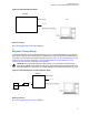
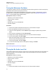
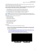
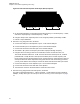
Table Of Contents
- Foreword
- General Safety and Installation Standards and Guidelines
- Declaration of Conformity
- MOTOTRBO SLR 1000 Repeater Supplemental Safety and Installation Requirements
- Environmental Information
- Document History
- Contents
- List of Figures
- List of Tables
- List of Procedures
- Related Publications
- Summary of Bands Available
- Commercial Warranty
- SLR 1000 Repeater
- SLR 1000 Satellite Receiver
- SLR 1000 Transceiver Board
- SLR 1000 Front Panel
- SLR 1000 Bottom Panel
- SLR 1000 Test Equipment And Service Aids
- SLR 1000 Performance Check or Testing
- SLR 1000 Programming and Tuning
- SLR 1000 Maintenance and Disassembly/Reassembly
- SLR 1000 Installation
- 10.1 Pre-Installation Considerations
- 10.2 SLR 1000 Repeater Package Contents
- 10.3 Mounting the SLR 1000 Repeater to a Wall or Ceiling
- 10.4 Mounting the SLR 1000 Repeater to a Pole
- 10.5 Electrical Connections
- 10.6 General Bonding and Grounding Requirements
- 10.7 General Cabling Requirements
- 10.8 Post Installation Checklist
- Appendix A: Accessories
- Appendix B: Replacement Parts Ordering
- Appendix C: Motorola Solutions Service Centers
- Appendix D: SLR 1000 Series Third-Party Controllers
- Appendix E: MOTOTRBO Repeater EME Assessment
- Glossary of Terms and Acronyms
- Alert tone
- Analog
- ASIC
- AUX
- Band
- CTCSS
- Clear
- Conventional
- CPS
- Default
- Digital
- DPL
- DSP
- EIA
- ESD
- EU
- FCC
- FM
- Frequency
- FRU
- FSK
- GNSS
- GPIO
- IC
- IF
- I/O
- kHz
- LCD
- LED
- MDC
- MHz
- MISO
- MOSI
- PA
- PC Board
- PFC
- PL
- Programming Cable
- PTT
- Radio Management
- Receiver
- Repeater
- RF
- RSSI
- Rx
- SCM
- SELV
- Signal
- SINAD
- SLR
- Spectrum
- SPI
- Squelch
- TOT
- TPL
- Transceiver
- Transmitter
- Trunking
- Tx
- UHF
- USB
- VCO
- VCTCXO
- VHF
- VIP
- VSWR
- WLAN
8.4
Tuning the Reference Oscillator
The reference oscillator of the SLR 1000 Repeater provides the timing reference used for all frequency
synthesizers and ensures their frequency accuracy.
This procedure is used to adjust the alignment of the reference oscillator. This alignment procedure
should be done as maintenance schedules and regulations require. See Repeater Tuning Setup
on
page 71 for the repeater tuning equipment setup.
Prerequisites: Obtain the following:
• Wattmeter (Communication Analyzer)
• Service monitor or counter
• 20 dB pad
• Standard Type A to Type B USB cable
• Personal computer
Procedure:
1 Connect the repeater transmitter antenna port to a Communication Analyzer.
2 Power the repeater from either an AC or DC source.
3 Launch the Tuner application, and click Read to begin reading the repeater tuning software
values.
4 In the tree view, select TX, then select Ref Oscillator.
5 Configure the currently operating frequency into the Communications Analyzer.
6 To key up the repeater, click PTT Toggle.
7 Adjust the working softpot value until the frequency is within the performance specifications (+/-
40 Hz for UHF) from the frequency point.
8 To de-key the repeater, click PTT Toggle.
9 To save the tuned softpot value into the repeater codeplug, click Write.
Return to Process
SLR 1000 Programming and Tuning on page 70
8.5
Tuning the Rx Audio Level Set
The procedure outlined in this section is used to set the receive output audio level from the repeater for
a given RF deviation of the received RF signal. Perform this procedure any time the Rx audio level
requires adjustment.
Prerequisites: Obtain the following:
• Wattmeter (Communication Analyzer)
• Service monitor or counter
• 20 dB pad
• Standard Type A to Type B USB cable
• Personal computer
Procedure:
1 Connect the repeater receiver antenna port to the Communication Analyzer.
MN003557A01-AF
Chapter 8: SLR 1000 Programming and Tuning
72