
Installation Manual
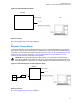
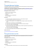
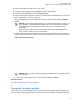
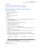
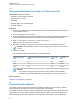
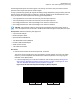
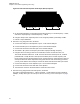
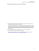
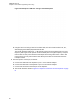
Table Of Contents
- Foreword
- General Safety and Installation Standards and Guidelines
- Declaration of Conformity
- MOTOTRBO SLR 1000 Repeater Supplemental Safety and Installation Requirements
- Environmental Information
- Document History
- Contents
- List of Figures
- List of Tables
- List of Procedures
- Related Publications
- Summary of Bands Available
- Commercial Warranty
- SLR 1000 Repeater
- SLR 1000 Satellite Receiver
- SLR 1000 Transceiver Board
- SLR 1000 Front Panel
- SLR 1000 Bottom Panel
- SLR 1000 Test Equipment And Service Aids
- SLR 1000 Performance Check or Testing
- SLR 1000 Programming and Tuning
- SLR 1000 Maintenance and Disassembly/Reassembly
- SLR 1000 Installation
- 10.1 Pre-Installation Considerations
- 10.2 SLR 1000 Repeater Package Contents
- 10.3 Mounting the SLR 1000 Repeater to a Wall or Ceiling
- 10.4 Mounting the SLR 1000 Repeater to a Pole
- 10.5 Electrical Connections
- 10.6 General Bonding and Grounding Requirements
- 10.7 General Cabling Requirements
- 10.8 Post Installation Checklist
- Appendix A: Accessories
- Appendix B: Replacement Parts Ordering
- Appendix C: Motorola Solutions Service Centers
- Appendix D: SLR 1000 Series Third-Party Controllers
- Appendix E: MOTOTRBO Repeater EME Assessment
- Glossary of Terms and Acronyms
- Alert tone
- Analog
- ASIC
- AUX
- Band
- CTCSS
- Clear
- Conventional
- CPS
- Default
- Digital
- DPL
- DSP
- EIA
- ESD
- EU
- FCC
- FM
- Frequency
- FRU
- FSK
- GNSS
- GPIO
- IC
- IF
- I/O
- kHz
- LCD
- LED
- MDC
- MHz
- MISO
- MOSI
- PA
- PC Board
- PFC
- PL
- Programming Cable
- PTT
- Radio Management
- Receiver
- Repeater
- RF
- RSSI
- Rx
- SCM
- SELV
- Signal
- SINAD
- SLR
- Spectrum
- SPI
- Squelch
- TOT
- TPL
- Transceiver
- Transmitter
- Trunking
- Tx
- UHF
- USB
- VCO
- VCTCXO
- VHF
- VIP
- VSWR
- WLAN

Figure 20: Radio Management Setup
Station
Bottom Panel
13.6 V DC
Return to Process
SLR 1000 Programming and Tuning on page 70
8.3
Repeater Tuning Setup
A personal computer (PC) with a Windows operating system, and the MOTOTRBO Tuner application
are required to align the SLR 1000 Repeater. To perform the tuning procedures, the repeater must be
connected to the PC and the test equipment setup as shown in Figure 21: SLR 1000 Repeater Tuning
Equipment Setup on page 71 and Figure 11: SLR 1000 Repeater Transceiver Board Connector
Locations on page 49 for the connectors on the repeater.
CAUTION: The high-speed solid-state antenna switch is only operable in Extended Range
Direct Mode (ERDM) mode. Enable all channels as Extended Range Direct Mode before using
the MOTOTRBO Tuner application, or possible damage to the antenna switch board may occur.
Figure 21: SLR 1000 Repeater Tuning Equipment Setup
Station
Bottom Panel
13.6 V DC
Tx Input
Port
Wattmeter
20 dB Pad
Service Monitor
or Counter
Transmit
Return to Process
SLR 1000 Programming and Tuning on page
70
MN003557A01-AF
Chapter 8: SLR 1000 Programming and Tuning
71