
Installation Manual
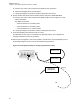

Table Of Contents
- Foreword
- General Safety and Installation Standards and Guidelines
- Declaration of Conformity
- MOTOTRBO SLR 1000 Repeater Supplemental Safety and Installation Requirements
- Environmental Information
- Document History
- Contents
- List of Figures
- List of Tables
- List of Procedures
- Related Publications
- Summary of Bands Available
- Commercial Warranty
- SLR 1000 Repeater
- SLR 1000 Satellite Receiver
- SLR 1000 Transceiver Board
- SLR 1000 Front Panel
- SLR 1000 Bottom Panel
- SLR 1000 Test Equipment And Service Aids
- SLR 1000 Performance Check or Testing
- SLR 1000 Programming and Tuning
- SLR 1000 Maintenance and Disassembly/Reassembly
- SLR 1000 Installation
- 10.1 Pre-Installation Considerations
- 10.2 SLR 1000 Repeater Package Contents
- 10.3 Mounting the SLR 1000 Repeater to a Wall or Ceiling
- 10.4 Mounting the SLR 1000 Repeater to a Pole
- 10.5 Electrical Connections
- 10.6 General Bonding and Grounding Requirements
- 10.7 General Cabling Requirements
- 10.8 Post Installation Checklist
- Appendix A: Accessories
- Appendix B: Replacement Parts Ordering
- Appendix C: Motorola Solutions Service Centers
- Appendix D: SLR 1000 Series Third-Party Controllers
- Appendix E: MOTOTRBO Repeater EME Assessment
- Glossary of Terms and Acronyms
- Alert tone
- Analog
- ASIC
- AUX
- Band
- CTCSS
- Clear
- Conventional
- CPS
- Default
- Digital
- DPL
- DSP
- EIA
- ESD
- EU
- FCC
- FM
- Frequency
- FRU
- FSK
- GNSS
- GPIO
- IC
- IF
- I/O
- kHz
- LCD
- LED
- MDC
- MHz
- MISO
- MOSI
- PA
- PC Board
- PFC
- PL
- Programming Cable
- PTT
- Radio Management
- Receiver
- Repeater
- RF
- RSSI
- Rx
- SCM
- SELV
- Signal
- SINAD
- SLR
- Spectrum
- SPI
- Squelch
- TOT
- TPL
- Transceiver
- Transmitter
- Trunking
- Tx
- UHF
- USB
- VCO
- VCTCXO
- VHF
- VIP
- VSWR
- WLAN
2 Set the service monitor to generate a 1.0
μV (-107 dBm) FM signal at the receiver frequency,
modulated by a 1 kHz tone at 3 kHz deviation for 25 /30 kHz channel spacing, or 1.5 kHz
deviation for 12.5 kHz channel spacing. The 1 kHz tone should be audible through the external
speaker. If no audio is heard, suspect the following:
• Faulty transceiver board
• Faulty service monitor-to-station RF cable
• Left panel to transceiver board cable unplugged
• Faulty left panel to transceiver board cable
3 If audio is heard (the audio volume can be adjusted on the rear of the HSN1006), look at the
oscilloscope window on the Aeroflex 3920 (or a separate O-Scope).
a Verify that the audio level sine wave measures between 0.75 to 1.5 Vpp.
b If not, connect to the tuner and increase the Rx audio level until the correct level is achieved.
If the level cannot be obtained, suspect a faulty transceiver board.
4 Move the BNC cable from the scope CH 1 input to the Audio 1 input.
5 Change the System Monitor injection signal level to the noted levels in Table 8: SLR 1000
Repeater Specifications on page 38.
6 Measure the receiver 12 dB SINAD sensitivity.
a If the SINAD level is less than 12 dB, suspect a faulty transceiver board.
7 Verify that all displays and measurements are correct.
The receiver circuitry may be considered to be operating properly. This completes the Verifying
Receiver Circuitry test procedure.
8 Remove the test equipment, restore the repeater to normal service, and (if applicable) return to
the troubleshooting flow chart to resume the troubleshooting sequence.
MN003557A01-AF
Chapter
7: SLR 1000 Performance Check or Testing
68