
Installation Manual

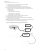

Table Of Contents
- Foreword
- General Safety and Installation Standards and Guidelines
- Declaration of Conformity
- MOTOTRBO SLR 1000 Repeater Supplemental Safety and Installation Requirements
- Environmental Information
- Document History
- Contents
- List of Figures
- List of Tables
- List of Procedures
- Related Publications
- Summary of Bands Available
- Commercial Warranty
- SLR 1000 Repeater
- SLR 1000 Satellite Receiver
- SLR 1000 Transceiver Board
- SLR 1000 Front Panel
- SLR 1000 Bottom Panel
- SLR 1000 Test Equipment And Service Aids
- SLR 1000 Performance Check or Testing
- SLR 1000 Programming and Tuning
- SLR 1000 Maintenance and Disassembly/Reassembly
- SLR 1000 Installation
- 10.1 Pre-Installation Considerations
- 10.2 SLR 1000 Repeater Package Contents
- 10.3 Mounting the SLR 1000 Repeater to a Wall or Ceiling
- 10.4 Mounting the SLR 1000 Repeater to a Pole
- 10.5 Electrical Connections
- 10.6 General Bonding and Grounding Requirements
- 10.7 General Cabling Requirements
- 10.8 Post Installation Checklist
- Appendix A: Accessories
- Appendix B: Replacement Parts Ordering
- Appendix C: Motorola Solutions Service Centers
- Appendix D: SLR 1000 Series Third-Party Controllers
- Appendix E: MOTOTRBO Repeater EME Assessment
- Glossary of Terms and Acronyms
- Alert tone
- Analog
- ASIC
- AUX
- Band
- CTCSS
- Clear
- Conventional
- CPS
- Default
- Digital
- DPL
- DSP
- EIA
- ESD
- EU
- FCC
- FM
- Frequency
- FRU
- FSK
- GNSS
- GPIO
- IC
- IF
- I/O
- kHz
- LCD
- LED
- MDC
- MHz
- MISO
- MOSI
- PA
- PC Board
- PFC
- PL
- Programming Cable
- PTT
- Radio Management
- Receiver
- Repeater
- RF
- RSSI
- Rx
- SCM
- SELV
- Signal
- SINAD
- SLR
- Spectrum
- SPI
- Squelch
- TOT
- TPL
- Transceiver
- Transmitter
- Trunking
- Tx
- UHF
- USB
- VCO
- VCTCXO
- VHF
- VIP
- VSWR
- WLAN

Return to Process
Transmitter Testing on page
64
7.3
Receiver Testing
Incorrect measurement signaling values of the SLR 1000 Repeater indicate a faulty module. Testing
the Receiver circuitry is done by injecting and measuring signals using a Service Monitor (or
equivalent). Measurement values within the acceptable range verify proper operation of the transceiver
board and circuitry.
CAUTION:
The SLR 1000 Repeater must be taken out of service to carry out performance testing
procedures. Unless the repeater is already out of service, perform the procedures during off-
peak hours to minimize disruption of service to the system subscribers.
If the repeater is operating as a repeater, the transmit output from the repeater must be
connected to a dummy load to prevent over-the-air broadcast during Receiver testing.
While most module faults can be detected by running the repeater diagnostics, Verifying Receiver
Circuitry
on page 67 provides a more traditional method of troubleshooting the Receiver circuitry and
allows the service technician to make minor adjustments and verify proper operation of the Receiver
circuitry on the repeater.
Return to Process
SLR 1000 Performance Check or Testing on page 64
Related Links
Required Receiver Test Equipment on page 67
Verifying Receiver Circuitry on page 67
7.3.1
Required Receiver Test Equipment
The following test equipment are required to perform the procedure:
• Aeroflex 3920 Digital Radio Test Set (or equivalent)
• Service Speaker (part no. HSN1006_)
• Station Rear Accessory Test Cable
• Dummy Load (50 Ω, repeater wattage or higher) required for repeaters only
• DB25/RJ-45 Adaptor
Return to Process
Receiver Testing on page 67
7.3.2
Verifying Receiver Circuitry
Perform this procedure to test the Receiver circuitry and verify that the measurement values are within
the acceptable range, and to verify proper operation of the transceiver board and circuitry.
Procedure:
1 Connect the equipment as shown in Figure 19: Test Equipment Setup for Verifying Receiver
Circuitry on page 69.
MN003557A01-AF
Chapter 7: SLR 1000 Performance Check or Testing
67