
Installation Manual

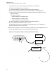

Table Of Contents
- Foreword
- General Safety and Installation Standards and Guidelines
- Declaration of Conformity
- MOTOTRBO SLR 1000 Repeater Supplemental Safety and Installation Requirements
- Environmental Information
- Document History
- Contents
- List of Figures
- List of Tables
- List of Procedures
- Related Publications
- Summary of Bands Available
- Commercial Warranty
- SLR 1000 Repeater
- SLR 1000 Satellite Receiver
- SLR 1000 Transceiver Board
- SLR 1000 Front Panel
- SLR 1000 Bottom Panel
- SLR 1000 Test Equipment And Service Aids
- SLR 1000 Performance Check or Testing
- SLR 1000 Programming and Tuning
- SLR 1000 Maintenance and Disassembly/Reassembly
- SLR 1000 Installation
- 10.1 Pre-Installation Considerations
- 10.2 SLR 1000 Repeater Package Contents
- 10.3 Mounting the SLR 1000 Repeater to a Wall or Ceiling
- 10.4 Mounting the SLR 1000 Repeater to a Pole
- 10.5 Electrical Connections
- 10.6 General Bonding and Grounding Requirements
- 10.7 General Cabling Requirements
- 10.8 Post Installation Checklist
- Appendix A: Accessories
- Appendix B: Replacement Parts Ordering
- Appendix C: Motorola Solutions Service Centers
- Appendix D: SLR 1000 Series Third-Party Controllers
- Appendix E: MOTOTRBO Repeater EME Assessment
- Glossary of Terms and Acronyms
- Alert tone
- Analog
- ASIC
- AUX
- Band
- CTCSS
- Clear
- Conventional
- CPS
- Default
- Digital
- DPL
- DSP
- EIA
- ESD
- EU
- FCC
- FM
- Frequency
- FRU
- FSK
- GNSS
- GPIO
- IC
- IF
- I/O
- kHz
- LCD
- LED
- MDC
- MHz
- MISO
- MOSI
- PA
- PC Board
- PFC
- PL
- Programming Cable
- PTT
- Radio Management
- Receiver
- Repeater
- RF
- RSSI
- Rx
- SCM
- SELV
- Signal
- SINAD
- SLR
- Spectrum
- SPI
- Squelch
- TOT
- TPL
- Transceiver
- Transmitter
- Trunking
- Tx
- UHF
- USB
- VCO
- VCTCXO
- VHF
- VIP
- VSWR
- WLAN

a Press the PTT switch of the microphone and speak into the microphone.
b Verify that the display shows an audio signal.
c If the proper display is not obtained, suspect a faulty transceiver board.
8 Set the Aeroflex 3900 Series Communications System Analyzer for GEN/ MON MTR.
a Press the PTT switch of the microphone and speak loudly into the microphone to cause
maximum deviation.
The display should read:
•
4.60 kHz maximum for a 25 kHz system
• 3.68 kHz maximum for a 20 kHz system
• 2.30 kHz maximum for a 12.5 kHz system
b If the proper display is not obtained, suspect a faulty transceiver board.
9 Verify that all displays and measurements are correct.
The transmitter circuitry may be considered to be operating properly. This completes the
Verifying Transmitter Circuitry test procedure.
10 Remove the test equipment, restore the repeater to normal service, and (if applicable) return to
the troubleshooting flow chart to resume the troubleshooting sequence.
Figure 18: Test Equipment Setup for Verifying Transmitter Circuitry
Tx
Dummy Load
Power Meter
Microphone
(GMMN4063)
(Step 5)
T/R
MN003557A01-AF
Chapter 7: SLR 1000 Performance Check or Testing
66