
Installation Manual
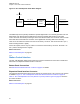
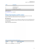
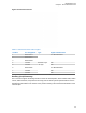
Table Of Contents
- Foreword
- General Safety and Installation Standards and Guidelines
- Declaration of Conformity
- MOTOTRBO SLR 1000 Repeater Supplemental Safety and Installation Requirements
- Environmental Information
- Document History
- Contents
- List of Figures
- List of Tables
- List of Procedures
- Related Publications
- Summary of Bands Available
- Commercial Warranty
- SLR 1000 Repeater
- SLR 1000 Satellite Receiver
- SLR 1000 Transceiver Board
- SLR 1000 Front Panel
- SLR 1000 Bottom Panel
- SLR 1000 Test Equipment And Service Aids
- SLR 1000 Performance Check or Testing
- SLR 1000 Programming and Tuning
- SLR 1000 Maintenance and Disassembly/Reassembly
- SLR 1000 Installation
- 10.1 Pre-Installation Considerations
- 10.2 SLR 1000 Repeater Package Contents
- 10.3 Mounting the SLR 1000 Repeater to a Wall or Ceiling
- 10.4 Mounting the SLR 1000 Repeater to a Pole
- 10.5 Electrical Connections
- 10.6 General Bonding and Grounding Requirements
- 10.7 General Cabling Requirements
- 10.8 Post Installation Checklist
- Appendix A: Accessories
- Appendix B: Replacement Parts Ordering
- Appendix C: Motorola Solutions Service Centers
- Appendix D: SLR 1000 Series Third-Party Controllers
- Appendix E: MOTOTRBO Repeater EME Assessment
- Glossary of Terms and Acronyms
- Alert tone
- Analog
- ASIC
- AUX
- Band
- CTCSS
- Clear
- Conventional
- CPS
- Default
- Digital
- DPL
- DSP
- EIA
- ESD
- EU
- FCC
- FM
- Frequency
- FRU
- FSK
- GNSS
- GPIO
- IC
- IF
- I/O
- kHz
- LCD
- LED
- MDC
- MHz
- MISO
- MOSI
- PA
- PC Board
- PFC
- PL
- Programming Cable
- PTT
- Radio Management
- Receiver
- Repeater
- RF
- RSSI
- Rx
- SCM
- SELV
- Signal
- SINAD
- SLR
- Spectrum
- SPI
- Squelch
- TOT
- TPL
- Transceiver
- Transmitter
- Trunking
- Tx
- UHF
- USB
- VCO
- VCTCXO
- VHF
- VIP
- VSWR
- WLAN

Figure 12: SLR 1000 Repeater Audio Block Diagram
TI DM8148
(DSP Core)
TI AIC3204
Audio
Codec
Accessory Connector
I²C (2)
Audio SSI (4)
TX Audio (Pin 1)
RX Audio (Pin 7)
RFIC SSI (4)
RX Audio
The DM8148 processor primarily handles the repeater digital audio. The TX RFIC generates a 24.576
MHz master clock (MCLK) that the DM8148 uses to drive its McASP SSI interface for the audio
codecs. The bulk of the audio processing is done in the DaVinci’s DSP core. The audio codecs contain
DACs and ADCs and handle the conversion of the digital audio to analog audio and conversely.
There is one TX audio line routed in from the rear accessory connector. This line is TX Audio 1 (Pin 1,
used for analog and slot 1 digital).
For the RX outputs, there is only one, which is connected to the accessory connector. RX Audio 1 on
Pin 7 (used for analog and slot 1 digital).
Return to Process
Station Control Subsystem on page 53
3.4.2
Station Control Interface
The SLR 1000 Repeater Station Control Interface connects to the Ethernet connection on the Bottom
Panel and to the Expansion Board Interface connection.
Bottom Panel Connections
See Bottom Panel Interfaces and Pin Location on page 57 for details.
Expansion Board Interface Connector
The expansion board interface uses a 30-pin vertical Low Insertion Force (LIF) connector. The location
is detailed in Figure 11: SLR 1000 Repeater Transceiver Board Connector Locations on page 49.
Table 11: SLR 1000 Repeater Front View (without Top Cover) Callout Legend on page 49 shows the
pin number locations.
Return to Process
Station Control Subsystem on page 53
MN003557A01-AF
Chapter 3: SLR 1000 Transceiver Board
54