
Installation Manual
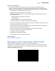

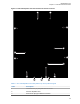
Table Of Contents
- Foreword
- General Safety and Installation Standards and Guidelines
- Declaration of Conformity
- MOTOTRBO SLR 1000 Repeater Supplemental Safety and Installation Requirements
- Environmental Information
- Document History
- Contents
- List of Figures
- List of Tables
- List of Procedures
- Related Publications
- Summary of Bands Available
- Commercial Warranty
- SLR 1000 Repeater
- SLR 1000 Satellite Receiver
- SLR 1000 Transceiver Board
- SLR 1000 Front Panel
- SLR 1000 Bottom Panel
- SLR 1000 Test Equipment And Service Aids
- SLR 1000 Performance Check or Testing
- SLR 1000 Programming and Tuning
- SLR 1000 Maintenance and Disassembly/Reassembly
- SLR 1000 Installation
- 10.1 Pre-Installation Considerations
- 10.2 SLR 1000 Repeater Package Contents
- 10.3 Mounting the SLR 1000 Repeater to a Wall or Ceiling
- 10.4 Mounting the SLR 1000 Repeater to a Pole
- 10.5 Electrical Connections
- 10.6 General Bonding and Grounding Requirements
- 10.7 General Cabling Requirements
- 10.8 Post Installation Checklist
- Appendix A: Accessories
- Appendix B: Replacement Parts Ordering
- Appendix C: Motorola Solutions Service Centers
- Appendix D: SLR 1000 Series Third-Party Controllers
- Appendix E: MOTOTRBO Repeater EME Assessment
- Glossary of Terms and Acronyms
- Alert tone
- Analog
- ASIC
- AUX
- Band
- CTCSS
- Clear
- Conventional
- CPS
- Default
- Digital
- DPL
- DSP
- EIA
- ESD
- EU
- FCC
- FM
- Frequency
- FRU
- FSK
- GNSS
- GPIO
- IC
- IF
- I/O
- kHz
- LCD
- LED
- MDC
- MHz
- MISO
- MOSI
- PA
- PC Board
- PFC
- PL
- Programming Cable
- PTT
- Radio Management
- Receiver
- Repeater
- RF
- RSSI
- Rx
- SCM
- SELV
- Signal
- SINAD
- SLR
- Spectrum
- SPI
- Squelch
- TOT
- TPL
- Transceiver
- Transmitter
- Trunking
- Tx
- UHF
- USB
- VCO
- VCTCXO
- VHF
- VIP
- VSWR
- WLAN

Label Description
4 Transmitter RF (Tx) Output Cable Port
5 Jumper Connection to enable external on/off function
6 Bonding Ground Connection
7 DC Power Inlet
8 Header Connection for optional antenna switch
9 Aux/Accessory Port
10 Ethernet Port
11 USB Port Programming Interface
12 Option Dependent 1 and 2
13 Expansion Board Connection (for future use)
14 Receiver RF (Rx) Input Cable Port
15 Front Panel Flex Connector
Return to Process
Transceiver Board Description on page 48
Related Links
External On/Off Function on page 50
3.1.2.1
External On/Off Function
The external on/off function allows a user to control the SLR 1000 Repeater through an external switch
if it is inconvenient to disrupt the main DC connection.
If the jumper is in the default position (across pins 1 and 2), the repeater is always On as long as DC is
connected to a DC power inlet. However, if the jumper is across pins 2 and 3, then DC power must be
supplied to pin 3 on the AUX connector (10.8–15.6 V) to enable the repeater.
Return to Process
Input and Output Connections on page
48
3.2
Receiver Subsystem
The Transceiver board includes the receiver circuitry for the station. A cable connects the board
connector to an N-type connector on the upper left-hand side of the repeater.
See Figure 11: SLR 1000 Repeater Transceiver Board Connector Locations on page 49 for the
location of the Receiver RF (Rx) Input Cable Port connector. The receiver section performs highly
selective bandpass filtering and dual down-conversion of the desired RF signal. A custom Receiver IC
then performs an analog-to-digital conversion of the desired received signal and outputs the digitized
signal to the controller section through a serial synchronous interface. Included in the receiver section
is:
Frequency Synthesizer Circuitry
Consists of a phase-locked loop and Voltage-Controlled Oscillator (VCO), generates the first LO
injection signal.
MN003557A01-AF
Chapter
3: SLR 1000 Transceiver Board
50