
Installation Manual
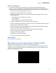
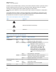

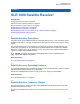
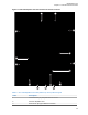
Table Of Contents
- Foreword
- General Safety and Installation Standards and Guidelines
- Declaration of Conformity
- MOTOTRBO SLR 1000 Repeater Supplemental Safety and Installation Requirements
- Environmental Information
- Document History
- Contents
- List of Figures
- List of Tables
- List of Procedures
- Related Publications
- Summary of Bands Available
- Commercial Warranty
- SLR 1000 Repeater
- SLR 1000 Satellite Receiver
- SLR 1000 Transceiver Board
- SLR 1000 Front Panel
- SLR 1000 Bottom Panel
- SLR 1000 Test Equipment And Service Aids
- SLR 1000 Performance Check or Testing
- SLR 1000 Programming and Tuning
- SLR 1000 Maintenance and Disassembly/Reassembly
- SLR 1000 Installation
- 10.1 Pre-Installation Considerations
- 10.2 SLR 1000 Repeater Package Contents
- 10.3 Mounting the SLR 1000 Repeater to a Wall or Ceiling
- 10.4 Mounting the SLR 1000 Repeater to a Pole
- 10.5 Electrical Connections
- 10.6 General Bonding and Grounding Requirements
- 10.7 General Cabling Requirements
- 10.8 Post Installation Checklist
- Appendix A: Accessories
- Appendix B: Replacement Parts Ordering
- Appendix C: Motorola Solutions Service Centers
- Appendix D: SLR 1000 Series Third-Party Controllers
- Appendix E: MOTOTRBO Repeater EME Assessment
- Glossary of Terms and Acronyms
- Alert tone
- Analog
- ASIC
- AUX
- Band
- CTCSS
- Clear
- Conventional
- CPS
- Default
- Digital
- DPL
- DSP
- EIA
- ESD
- EU
- FCC
- FM
- Frequency
- FRU
- FSK
- GNSS
- GPIO
- IC
- IF
- I/O
- kHz
- LCD
- LED
- MDC
- MHz
- MISO
- MOSI
- PA
- PC Board
- PFC
- PL
- Programming Cable
- PTT
- Radio Management
- Receiver
- Repeater
- RF
- RSSI
- Rx
- SCM
- SELV
- Signal
- SINAD
- SLR
- Spectrum
- SPI
- Squelch
- TOT
- TPL
- Transceiver
- Transmitter
- Trunking
- Tx
- UHF
- USB
- VCO
- VCTCXO
- VHF
- VIP
- VSWR
- WLAN

Chapter 3
SLR 1000 Transceiver Board
Related Links
Transceiver Board Description on page 48
Receiver Subsystem on page 50
Transmitter Subsystem on page
52
Station Control Subsystem on page 53
3.1
Transceiver Board Description
A general description, identification of inputs and outputs, and functional theory of operation for the
Transceiver board are provided. The information provided is sufficient to give service personnel a
functional understanding of the module, allowing maintenance and troubleshooting at the module level.
Return to Process
SLR 1000 Transceiver Board on page 48
Related Links
Transceiver Board General Description on page 48
Input and Output Connections on page 48
3.1.1
Transceiver Board General Description
The Transceiver board provides the receiver, transmitter, and station control functionality for the
repeater. Additionally, the external connections to the station are connected directly to the transceiver
board.
Return to Process
Transceiver Board Description on page 48
3.1.2
Input and Output Connections
The SLR 1000 Repeater has input and output connections on the transceiver board.
See Figure 11: SLR 1000 Repeater Transceiver Board Connector Locations on page 49 and Table
11: SLR 1000 Repeater Front View (without Top Cover) Callout Legend on page 49 for the locations
and descriptions of the input and output external connections.
MN003557A01-AF
Chapter
3: SLR 1000 Transceiver Board
48