
Installation Manual

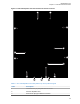
Table Of Contents
- Foreword
- General Safety and Installation Standards and Guidelines
- Declaration of Conformity
- MOTOTRBO SLR 1000 Repeater Supplemental Safety and Installation Requirements
- Environmental Information
- Document History
- Contents
- List of Figures
- List of Tables
- List of Procedures
- Related Publications
- Summary of Bands Available
- Commercial Warranty
- SLR 1000 Repeater
- SLR 1000 Satellite Receiver
- SLR 1000 Transceiver Board
- SLR 1000 Front Panel
- SLR 1000 Bottom Panel
- SLR 1000 Test Equipment And Service Aids
- SLR 1000 Performance Check or Testing
- SLR 1000 Programming and Tuning
- SLR 1000 Maintenance and Disassembly/Reassembly
- SLR 1000 Installation
- 10.1 Pre-Installation Considerations
- 10.2 SLR 1000 Repeater Package Contents
- 10.3 Mounting the SLR 1000 Repeater to a Wall or Ceiling
- 10.4 Mounting the SLR 1000 Repeater to a Pole
- 10.5 Electrical Connections
- 10.6 General Bonding and Grounding Requirements
- 10.7 General Cabling Requirements
- 10.8 Post Installation Checklist
- Appendix A: Accessories
- Appendix B: Replacement Parts Ordering
- Appendix C: Motorola Solutions Service Centers
- Appendix D: SLR 1000 Series Third-Party Controllers
- Appendix E: MOTOTRBO Repeater EME Assessment
- Glossary of Terms and Acronyms
- Alert tone
- Analog
- ASIC
- AUX
- Band
- CTCSS
- Clear
- Conventional
- CPS
- Default
- Digital
- DPL
- DSP
- EIA
- ESD
- EU
- FCC
- FM
- Frequency
- FRU
- FSK
- GNSS
- GPIO
- IC
- IF
- I/O
- kHz
- LCD
- LED
- MDC
- MHz
- MISO
- MOSI
- PA
- PC Board
- PFC
- PL
- Programming Cable
- PTT
- Radio Management
- Receiver
- Repeater
- RF
- RSSI
- Rx
- SCM
- SELV
- Signal
- SINAD
- SLR
- Spectrum
- SPI
- Squelch
- TOT
- TPL
- Transceiver
- Transmitter
- Trunking
- Tx
- UHF
- USB
- VCO
- VCTCXO
- VHF
- VIP
- VSWR
- WLAN

Station Control Subsystem
The heart of the Station Control subsystem is the Texas Instruments DM8148 Host/ DSP
processor. In general, the Station Control Module (SCM) controls the entire coordination of the
repeater functions. Specifically, the Station Control subsystem provides for the following functions:
•
Contains and runs the preloaded repeater software
• Manages inbound and outbound RF and Audio traffic
• Provides an on-board USB port for local configuring, alignment, and diagnostics through the
following applications:
- Radio Management Configuration Client (RM)
- Tuner application
- Repeater Diagnostic and Control (RDAC) software
• Provides an Ethernet port for IP site connectivity and remote RDAC
• Provides General Purpose Input/Output (GPIO) connectivity for third-party controller interfaces
• Provides analog repeater audio connectivity
• Data and Control to the Receiver subsystem through the Serial Peripheral Interface (SPI) and
Synchronous Serial Interface (SSI) respectively
• Data and Control to the Exciter subsystem through the SPI and SSI respectively
• Control of the Transmitter’s set power through the SPI
• Configuration and fault management
• Generates the internal station reference
• Provides control of the front panel indicator LEDs.
Return to Process
SLR 1000 Repeater on page 28
1.6
Basic Repeater Level Troubleshooting – RDAC and LEDs
Diagnostic tests are available for the Transceiver of the SLR 1000 Repeater.
If a problem occurs during station operation, it is logged as an alarm that is read with the Repeater
Diagnostic and Control application (RDAC). See the following figure for the RDAC diagnostic screen.
Figure 8: RDAC Diagnostic Screen
MN003557A01-AF
Chapter 1: SLR 1000 Repeater
41