
Installation Manual
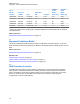
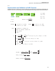
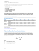
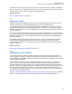
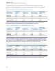
Table Of Contents
- Foreword
- General Safety and Installation Standards and Guidelines
- Declaration of Conformity
- MOTOTRBO SLR 1000 Repeater Supplemental Safety and Installation Requirements
- Environmental Information
- Document History
- Contents
- List of Figures
- List of Tables
- List of Procedures
- Related Publications
- Summary of Bands Available
- Commercial Warranty
- SLR 1000 Repeater
- SLR 1000 Satellite Receiver
- SLR 1000 Transceiver Board
- SLR 1000 Front Panel
- SLR 1000 Bottom Panel
- SLR 1000 Test Equipment And Service Aids
- SLR 1000 Performance Check or Testing
- SLR 1000 Programming and Tuning
- SLR 1000 Maintenance and Disassembly/Reassembly
- SLR 1000 Installation
- 10.1 Pre-Installation Considerations
- 10.2 SLR 1000 Repeater Package Contents
- 10.3 Mounting the SLR 1000 Repeater to a Wall or Ceiling
- 10.4 Mounting the SLR 1000 Repeater to a Pole
- 10.5 Electrical Connections
- 10.6 General Bonding and Grounding Requirements
- 10.7 General Cabling Requirements
- 10.8 Post Installation Checklist
- Appendix A: Accessories
- Appendix B: Replacement Parts Ordering
- Appendix C: Motorola Solutions Service Centers
- Appendix D: SLR 1000 Series Third-Party Controllers
- Appendix E: MOTOTRBO Repeater EME Assessment
- Glossary of Terms and Acronyms
- Alert tone
- Analog
- ASIC
- AUX
- Band
- CTCSS
- Clear
- Conventional
- CPS
- Default
- Digital
- DPL
- DSP
- EIA
- ESD
- EU
- FCC
- FM
- Frequency
- FRU
- FSK
- GNSS
- GPIO
- IC
- IF
- I/O
- kHz
- LCD
- LED
- MDC
- MHz
- MISO
- MOSI
- PA
- PC Board
- PFC
- PL
- Programming Cable
- PTT
- Radio Management
- Receiver
- Repeater
- RF
- RSSI
- Rx
- SCM
- SELV
- Signal
- SINAD
- SLR
- Spectrum
- SPI
- Squelch
- TOT
- TPL
- Transceiver
- Transmitter
- Trunking
- Tx
- UHF
- USB
- VCO
- VCTCXO
- VHF
- VIP
- VSWR
- WLAN

H
eff
shall be ecaluated using
H
eff
H
beam
H
beam
= 2· d ·tan(θ
3dB
/ 2)
H
beam
< L AND H
beam
<
L
Table B.17 – Definition of C(f)
=
L ≤ H
beam
<
where
MHz
3,5 +
6,3 +
1+
1,8
8,1
4,5
400
400
for d > 400mm
for d > 400mm
for d ≤ 400mm
for 200mm ≤ d ≤ 400mm
600
600
0,8d
0,8d
f
– 300
f
– 300
1+
300 to 900
900 to 5 000
f
C( f,d)
10
-4
m
3
/kg
B
B
B
B
B ≤ H
beam
B ≤ L
As shown, the formulas are valid for a specific frequency range and distances. Based on the device
and antenna characteristics the formulas are valid for evaluation of the upper bounds of localized and
whole-body average SAR for exposures within the main beam of the antenna (front direction). Since
this represents the most conservative exposure condition, the front direction compliance distance is
also applied for all other directions to define conservative compliance boundaries in those directions.
Return to Process
Exposure Prediction Model on page 134
MN003557A01-AF
Appendix
E: MOTOTRBO Repeater EME Assessment
136