
Installation Manual
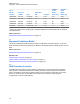
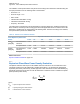
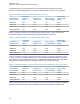
Table Of Contents
- Foreword
- General Safety and Installation Standards and Guidelines
- Declaration of Conformity
- MOTOTRBO SLR 1000 Repeater Supplemental Safety and Installation Requirements
- Environmental Information
- Document History
- Contents
- List of Figures
- List of Tables
- List of Procedures
- Related Publications
- Summary of Bands Available
- Commercial Warranty
- SLR 1000 Repeater
- SLR 1000 Satellite Receiver
- SLR 1000 Transceiver Board
- SLR 1000 Front Panel
- SLR 1000 Bottom Panel
- SLR 1000 Test Equipment And Service Aids
- SLR 1000 Performance Check or Testing
- SLR 1000 Programming and Tuning
- SLR 1000 Maintenance and Disassembly/Reassembly
- SLR 1000 Installation
- 10.1 Pre-Installation Considerations
- 10.2 SLR 1000 Repeater Package Contents
- 10.3 Mounting the SLR 1000 Repeater to a Wall or Ceiling
- 10.4 Mounting the SLR 1000 Repeater to a Pole
- 10.5 Electrical Connections
- 10.6 General Bonding and Grounding Requirements
- 10.7 General Cabling Requirements
- 10.8 Post Installation Checklist
- Appendix A: Accessories
- Appendix B: Replacement Parts Ordering
- Appendix C: Motorola Solutions Service Centers
- Appendix D: SLR 1000 Series Third-Party Controllers
- Appendix E: MOTOTRBO Repeater EME Assessment
- Glossary of Terms and Acronyms
- Alert tone
- Analog
- ASIC
- AUX
- Band
- CTCSS
- Clear
- Conventional
- CPS
- Default
- Digital
- DPL
- DSP
- EIA
- ESD
- EU
- FCC
- FM
- Frequency
- FRU
- FSK
- GNSS
- GPIO
- IC
- IF
- I/O
- kHz
- LCD
- LED
- MDC
- MHz
- MISO
- MOSI
- PA
- PC Board
- PFC
- PL
- Programming Cable
- PTT
- Radio Management
- Receiver
- Repeater
- RF
- RSSI
- Rx
- SCM
- SELV
- Signal
- SINAD
- SLR
- Spectrum
- SPI
- Squelch
- TOT
- TPL
- Transceiver
- Transmitter
- Trunking
- Tx
- UHF
- USB
- VCO
- VCTCXO
- VHF
- VIP
- VSWR
- WLAN

Appendix E
MOTOTRBO Repeater EME
Assessment
NOTICE: The examples in this Appendix apply to a UHF band system configuration. For
different frequency bands, applicable band-specific parameters should be employed to carry out
the computations yielding band-specific compliance boundaries.
Related Links
Executive Summary
on page 132
Device Characteristics on page 133
Exposure Prediction Model on page 134
Exposure Limits on page 139
EME Exposure Evaluation on page 139
Compliance Boundary Description on page 141
Product Put In Service on page 142
References on page 142
E.1
Executive Summary
Compliance versus EME (Electromagnetic Energy Exposure) limits is established with respect to the
ICNIRP guidelines [1] and U.S. FCC regulations [2-3] in a typical system configuration of the
MOTOTRBO SLR 1000 Repeater described in the following.
A computational assessment was carried out to provide an estimation of the EME exposure and
compliance distances relative to the SLR 1000 Repeater Model FCC ID ABZ99FT3096
AAR11JDGANQ1AN and FCC ID ABZ99FT4100, Model AAR11SDGANQ1AN) equipped with
HKAD4003, HKAD4004, HKAD4005, HKAE4003, HKAE4004, or HKAE4005 antennas for indoor
installation and with the Andrew DB408-B antenna for outdoor installations.
The following tables provide the compliance distances for general public and occupational-type
exposure, for the UHF frequency band, antennas, and other relevant parameters considered in this
analysis of typical system configurations:
Table 27: Indoor EME Compliance Distances Based on the UHF Evaluation Example (applicable
antennas: HKAE4003, HKAE4004, and HKAE4005)
Exposure Condition
Based on the Peak
1-g SAR FCC Limit
Based on the Peak
10-g SAR ICNIRP
Limit
Based on the Whole-
Body SAR Limit
General public expo-
sure
46 cm 20 cm 20 cm
Occupational-type ex-
posure
20 cm 20 cm 20 cm
MN003557A01-AF
Appendix
E: MOTOTRBO Repeater EME Assessment
132