
Installation Manual
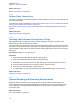

Table Of Contents
- Foreword
- General Safety and Installation Standards and Guidelines
- Declaration of Conformity
- MOTOTRBO SLR 1000 Repeater Supplemental Safety and Installation Requirements
- Environmental Information
- Document History
- Contents
- List of Figures
- List of Tables
- List of Procedures
- Related Publications
- Summary of Bands Available
- Commercial Warranty
- SLR 1000 Repeater
- SLR 1000 Satellite Receiver
- SLR 1000 Transceiver Board
- SLR 1000 Front Panel
- SLR 1000 Bottom Panel
- SLR 1000 Test Equipment And Service Aids
- SLR 1000 Performance Check or Testing
- SLR 1000 Programming and Tuning
- SLR 1000 Maintenance and Disassembly/Reassembly
- SLR 1000 Installation
- 10.1 Pre-Installation Considerations
- 10.2 SLR 1000 Repeater Package Contents
- 10.3 Mounting the SLR 1000 Repeater to a Wall or Ceiling
- 10.4 Mounting the SLR 1000 Repeater to a Pole
- 10.5 Electrical Connections
- 10.6 General Bonding and Grounding Requirements
- 10.7 General Cabling Requirements
- 10.8 Post Installation Checklist
- Appendix A: Accessories
- Appendix B: Replacement Parts Ordering
- Appendix C: Motorola Solutions Service Centers
- Appendix D: SLR 1000 Series Third-Party Controllers
- Appendix E: MOTOTRBO Repeater EME Assessment
- Glossary of Terms and Acronyms
- Alert tone
- Analog
- ASIC
- AUX
- Band
- CTCSS
- Clear
- Conventional
- CPS
- Default
- Digital
- DPL
- DSP
- EIA
- ESD
- EU
- FCC
- FM
- Frequency
- FRU
- FSK
- GNSS
- GPIO
- IC
- IF
- I/O
- kHz
- LCD
- LED
- MDC
- MHz
- MISO
- MOSI
- PA
- PC Board
- PFC
- PL
- Programming Cable
- PTT
- Radio Management
- Receiver
- Repeater
- RF
- RSSI
- Rx
- SCM
- SELV
- Signal
- SINAD
- SLR
- Spectrum
- SPI
- Squelch
- TOT
- TPL
- Transceiver
- Transmitter
- Trunking
- Tx
- UHF
- USB
- VCO
- VCTCXO
- VHF
- VIP
- VSWR
- WLAN

Figure 44: Assembled SLR 1000 Repeater Power Supply
Return to Process
Electrical Connections on page 108
10.5.4
Ground Connection
The SLR 1000 Repeater is equipped with a ground screw on the bottom panel.
Figure 41: SLR 1000 Repeater Bottom Panel Connector Names and Locations on page 109 shows the
location of the grounding screw. Connect the ground screw to the site ground point. The size of the
wire used for this connection must be 6 AWG minimum.
CAUTION: See the Motorola Quality Standards Fixed Network Equipment Installation Manual
R56 (which can be obtained by ordering CDROM 9880384V83), for complete information
regarding lightning protection.
The repeater should only be connected to a battery supply that is in accordance with the
applicable electrical codes for the end use country; for example, the National Electrical Code
ANSI/ NFPA No. 70 in the U.S.
Return to Process
Electrical Connections on page 108
10.5.5
RF Antenna Connections
The transmit and receive antenna RF connections are made using two separate connectors.
Coax cables from the receive and transmit antennas must be connected to their respective connectors.
The positions of these connectors are shown in Figure 2: SLR 1000 Repeater Left View on page 29
and Figure 3: SLR 1000 Repeater Right View on page 30. Their respective connector types are noted
in Table 2: SLR 1000 Repeater Left View Callout Legend on page 30 and Table 3: SLR 1000 Repeater
Right View Callout Legend on page 30.
When mounting an antenna directly to the repeater, the antenna must be positioned to extend either
above or in front of the repeater, not along the body of the repeater.
MN003557A01-AF
Chapter 10: SLR 1000 Installation
113