
Installation Manual
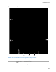
Table Of Contents
- Foreword
- General Safety and Installation Standards and Guidelines
- Declaration of Conformity
- MOTOTRBO SLR 1000 Repeater Supplemental Safety and Installation Requirements
- Environmental Information
- Document History
- Contents
- List of Figures
- List of Tables
- List of Procedures
- Related Publications
- Summary of Bands Available
- Commercial Warranty
- SLR 1000 Repeater
- SLR 1000 Satellite Receiver
- SLR 1000 Transceiver Board
- SLR 1000 Front Panel
- SLR 1000 Bottom Panel
- SLR 1000 Test Equipment And Service Aids
- SLR 1000 Performance Check or Testing
- SLR 1000 Programming and Tuning
- SLR 1000 Maintenance and Disassembly/Reassembly
- SLR 1000 Installation
- 10.1 Pre-Installation Considerations
- 10.2 SLR 1000 Repeater Package Contents
- 10.3 Mounting the SLR 1000 Repeater to a Wall or Ceiling
- 10.4 Mounting the SLR 1000 Repeater to a Pole
- 10.5 Electrical Connections
- 10.6 General Bonding and Grounding Requirements
- 10.7 General Cabling Requirements
- 10.8 Post Installation Checklist
- Appendix A: Accessories
- Appendix B: Replacement Parts Ordering
- Appendix C: Motorola Solutions Service Centers
- Appendix D: SLR 1000 Series Third-Party Controllers
- Appendix E: MOTOTRBO Repeater EME Assessment
- Glossary of Terms and Acronyms
- Alert tone
- Analog
- ASIC
- AUX
- Band
- CTCSS
- Clear
- Conventional
- CPS
- Default
- Digital
- DPL
- DSP
- EIA
- ESD
- EU
- FCC
- FM
- Frequency
- FRU
- FSK
- GNSS
- GPIO
- IC
- IF
- I/O
- kHz
- LCD
- LED
- MDC
- MHz
- MISO
- MOSI
- PA
- PC Board
- PFC
- PL
- Programming Cable
- PTT
- Radio Management
- Receiver
- Repeater
- RF
- RSSI
- Rx
- SCM
- SELV
- Signal
- SINAD
- SLR
- Spectrum
- SPI
- Squelch
- TOT
- TPL
- Transceiver
- Transmitter
- Trunking
- Tx
- UHF
- USB
- VCO
- VCTCXO
- VHF
- VIP
- VSWR
- WLAN

Location Connector Type Function(s)
3 2.1 X 5.5 OD
Barrel Connector
DC Power Inlet
4 RJ-45 – Aux/
Accessory
Rx Audio, Tx Audio, PTT, 1 PPS, and GPIO
5 RJ-45 – Ethernet Network
6 Type B USB
Socket
Programming Interface
7 Option Depend-
ent
Option Dependent 1 and 2
8 N-Type – Fe-
male
Transmitter RF (Tx)
Return to Process
SLR 1000 Installation on page
93
Related Links
Connecting the DC Input Power on page 110
Connecting the Indoor Adapter AC Input Power on page 111
Assembling an Outdoor Power Supply on page 111
Ground Connection on page 113
RF Antenna Connections on page 113
System Cable Connections on page 114
Installing Cable Grommet Connectors or Plugs on page 114
10.5.1
Connecting the DC Input Power
Each repeater comes with a 3-meter DC input cable with a barrel type connector output that connects
to the repeater.
The DC source power is connected to the repeater through the DC power inlet connector as shown in
Figure 41: SLR 1000 Repeater Bottom Panel Connector Names and Locations on page 109.
Longer runs of DC power require a junction box or splice connection of some type near the repeater so
that larger gauge cable can be used and then connected to the DC barrel cable (cut to length as
needed). Cable gauge and length should be carefully selected to ensure that nominal voltage at the
supply does not fall below minimum specified.
The DC source must be located in the same building as the repeater, and it must meet the
requirements of an SELV circuit.
CAUTION: Ensure that the appropriate voltage is connected with a nominal 13.6 VDC (10.8 –
15.6 VDC).
To provide adequate isolation and prevent EMC issues from impacting function, ensure that the
placement of the DC power source and/or routing of the DC cable maintain a distance of a
minimum of 0.5 m from the repeater antenna.
Procedure:
1 To seal the cable, thread the gland nut, then the cable gland over the barrel connector.
2 Insert the connector into the repeater then thread in the cable gland. Torque the cable gland to
55 in.-lb to compress.
MN003557A01-AF
Chapter 10: SLR 1000 Installation
110