
Installation Manual


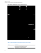


Table Of Contents
- Foreword
- General Safety and Installation Standards and Guidelines
- Declaration of Conformity
- Declaration of Compliance for the Use of Distress and Safety Frequencies
- MOTOTRBO SLR 1000 Repeater Supplemental Safety and Installation Requirements
- Environmental Information
- Document History
- Contents
- List of Figures
- List of Tables
- List of Procedures
- Related Publications
- Summary of Bands Available
- Commercial Warranty
- SLR 1000 Repeater
- SLR 1000 Satellite Receiver
- SLR 1000 Transceiver Board
- SLR 1000 Front Panel
- SLR 1000 Bottom Panel
- SLR 1000 Test Equipment And Service Aids
- SLR 1000 Performance Check or Testing
- SLR 1000 Programming and Tuning
- SLR 1000 Maintenance and Disassembly/Reassembly
- SLR 1000 Installation
- 10.1 Pre-Installation Considerations
- 10.2 SLR 1000 Repeater Package Contents
- 10.3 Mounting the SLR 1000 Repeater to a Wall or Ceiling
- 10.4 Mounting the SLR 1000 Repeater to a Pole
- 10.5 Electrical Connections
- 10.6 General Bonding and Grounding Requirements
- 10.7 General Cabling Requirements
- 10.8 Post Installation Checklist
- Appendix A: Accessories
- Appendix B: Replacement Parts Ordering
- Appendix C: Motorola Solutions Service Centers
- Appendix D: SLR 1000 Series Third-Party Controllers
- Appendix E: MOTOTRBO Repeater EME Assessment
- Glossary of Terms and Acronyms
- Alert tone
- Analog
- ASIC
- AUX
- Band
- CTCSS
- Clear
- Conventional
- CPS
- Default
- Digital
- DPL
- DSP
- EIA
- ESD
- EU
- FCC
- FM
- Frequency
- FRU
- FSK
- GNSS
- GPIO
- IC
- IF
- I/O
- kHz
- LCD
- LED
- MDC
- MHz
- MISO
- MOSI
- PA
- PC Board
- PFC
- PL
- Programming Cable
- PTT
- Radio Management
- Receiver
- Repeater
- RF
- RSSI
- Rx
- SCM
- SELV
- Signal
- SINAD
- SLR
- Spectrum
- SPI
- Squelch
- TOT
- TPL
- Transceiver
- Transmitter
- Trunking
- Tx
- UHF
- USB
- VCO
- VCTCXO
- VHF
- VIP
- VSWR
- WLAN

Return to Process
SLR 1000 Maintenance and Disassembly/Reassembly
on page 83
9.4
Installing a Duplexer
Install a duplexer into the SLR 1000 Repeater when transmitting and receiving using one antenna.
Prerequisites: Obtain the following:
• Duplexer kit
• Four M3 screws (obtained from the repeater package)
• T20 bit screwdriver
• T10 bit screwdriver
• ¾ in. deep well socket
NOTICE: The duplexer must be tuned before being installed. See Tuning a Duplexer Module
on
page 77.
Procedure:
1 Turn off power to the repeater.
2 Disassemble the repeater, as follows:
a Turn the repeater over and remove the four M4 screws using a T20 bit.
b Hold the cover onto the chassis and carefully turn the repeater over.
c Slowly remove the top cover, making sure not to damage the front panel flex cable.
3 Disconnect the following cables. See Figure 28: SLR 1000 Repeater Front View (without top
cover)
on page 86.
a Disconnect the front panel flex cable from the front panel display board.
b Cut the tie wrap that secures the Tx and Rx cables.
c Disconnect the Rx cable from the Rx input board connection by gently pulling up.
d Disconnect the Tx cable from the Tx output board connection by gently pulling up.
e Remove the Tx cable by either cutting (recommended) the cable from the Tx output port or
tie wrapping the cable.
CAUTION: The Tx cable must not touch any components on the board.
f Remove the Rx cable from the Rx port opening in the chassis.
MN003557A01-AF
Chapter 9: SLR 1000 Maintenance and Disassembly/Reassembly
85