
Installation Manual


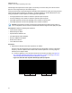

Table Of Contents
- Foreword
- General Safety and Installation Standards and Guidelines
- Declaration of Conformity
- Declaration of Compliance for the Use of Distress and Safety Frequencies
- MOTOTRBO SLR 1000 Repeater Supplemental Safety and Installation Requirements
- Environmental Information
- Document History
- Contents
- List of Figures
- List of Tables
- List of Procedures
- Related Publications
- Summary of Bands Available
- Commercial Warranty
- SLR 1000 Repeater
- SLR 1000 Satellite Receiver
- SLR 1000 Transceiver Board
- SLR 1000 Front Panel
- SLR 1000 Bottom Panel
- SLR 1000 Test Equipment And Service Aids
- SLR 1000 Performance Check or Testing
- SLR 1000 Programming and Tuning
- SLR 1000 Maintenance and Disassembly/Reassembly
- SLR 1000 Installation
- 10.1 Pre-Installation Considerations
- 10.2 SLR 1000 Repeater Package Contents
- 10.3 Mounting the SLR 1000 Repeater to a Wall or Ceiling
- 10.4 Mounting the SLR 1000 Repeater to a Pole
- 10.5 Electrical Connections
- 10.6 General Bonding and Grounding Requirements
- 10.7 General Cabling Requirements
- 10.8 Post Installation Checklist
- Appendix A: Accessories
- Appendix B: Replacement Parts Ordering
- Appendix C: Motorola Solutions Service Centers
- Appendix D: SLR 1000 Series Third-Party Controllers
- Appendix E: MOTOTRBO Repeater EME Assessment
- Glossary of Terms and Acronyms
- Alert tone
- Analog
- ASIC
- AUX
- Band
- CTCSS
- Clear
- Conventional
- CPS
- Default
- Digital
- DPL
- DSP
- EIA
- ESD
- EU
- FCC
- FM
- Frequency
- FRU
- FSK
- GNSS
- GPIO
- IC
- IF
- I/O
- kHz
- LCD
- LED
- MDC
- MHz
- MISO
- MOSI
- PA
- PC Board
- PFC
- PL
- Programming Cable
- PTT
- Radio Management
- Receiver
- Repeater
- RF
- RSSI
- Rx
- SCM
- SELV
- Signal
- SINAD
- SLR
- Spectrum
- SPI
- Squelch
- TOT
- TPL
- Transceiver
- Transmitter
- Trunking
- Tx
- UHF
- USB
- VCO
- VCTCXO
- VHF
- VIP
- VSWR
- WLAN

deviation for a given transmit audio level. Perform this procedure any time the transmitter audio level
requires adjustment.
Prerequisites: Obtain the following:
•
Wattmeter (Communication Analyzer)
• Service monitor or counter
• 20 dB pad
• Standard Type A to Type B USB cable
• Personal computer
Procedure:
1 Connect the repeater transmitter antenna port to the Communication Analyzer.
2 Power the repeater from a DC source.
3 Apply a 1 kHz signal at the desired input level to Pin 1 (in reference to ground) on the Aux
connector. The ground connection provided by the Aux connector is Pin 4. See Figure 22:
Auxiliary Connector on page 74
NOTICE: Optimally, load Pin 1 with the application source impedance used during
normal operation of the repeater.
4 Launch the Tuner application and click Read to read the softpot values.
5 In the tree view, select TX, then select Tx Audio Level.
6 Enter the tuning frequency into the Communication Analyzer (the value displayed in the Tuner
application under the heading Frequency Points.
7 To key up the repeater, click PTT Toggle.
8 Adjust the softpot value until the desired receive audio level is achieved at Pin 7 (in reference to
ground) on the Aux connector.
The ground connection provided by the Aux connector is Pin 4.
NOTICE: The Tuner aligns this parameter in a 12.5 kHz channel spacing, so 60% is 1.5
kHz of deviation. If Radio Management (RM) is set for 25 kHz operation, the repeater
automatically scales the deviation by a factor of two when it is outside the Tuner
application.
9 To de-key the repeater, click PTT Toggle.
10 To save the new tuned softpot value into the repeater codeplug, click Write.
Return to Process
SLR 1000 Programming and Tuning on page
71
8.7
Modulation Limit Alignment
Modulation is a change or alteration in the signal. Any aspect of the signal can be changed, such as
amplitude, frequency, phase, timing or repetition rate of pulses. Aligning the modulation limit sets the
RF carrier wave of the frequency bandwidth of the SLR 1000 Repeater.
NOTICE: A modulation limit alignment is always required when the repeater is in digital mode.
This alignment is not required if the repeater is used in repeat mode.
Return to Process
SLR 1000 Programming and Tuning on page
71
MN003557A01-AF
Chapter 8: SLR 1000 Programming and Tuning
75