
Installation Manual


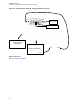
Table Of Contents
- Foreword
- General Safety and Installation Standards and Guidelines
- Declaration of Conformity
- Declaration of Compliance for the Use of Distress and Safety Frequencies
- MOTOTRBO SLR 1000 Repeater Supplemental Safety and Installation Requirements
- Environmental Information
- Document History
- Contents
- List of Figures
- List of Tables
- List of Procedures
- Related Publications
- Summary of Bands Available
- Commercial Warranty
- SLR 1000 Repeater
- SLR 1000 Satellite Receiver
- SLR 1000 Transceiver Board
- SLR 1000 Front Panel
- SLR 1000 Bottom Panel
- SLR 1000 Test Equipment And Service Aids
- SLR 1000 Performance Check or Testing
- SLR 1000 Programming and Tuning
- SLR 1000 Maintenance and Disassembly/Reassembly
- SLR 1000 Installation
- 10.1 Pre-Installation Considerations
- 10.2 SLR 1000 Repeater Package Contents
- 10.3 Mounting the SLR 1000 Repeater to a Wall or Ceiling
- 10.4 Mounting the SLR 1000 Repeater to a Pole
- 10.5 Electrical Connections
- 10.6 General Bonding and Grounding Requirements
- 10.7 General Cabling Requirements
- 10.8 Post Installation Checklist
- Appendix A: Accessories
- Appendix B: Replacement Parts Ordering
- Appendix C: Motorola Solutions Service Centers
- Appendix D: SLR 1000 Series Third-Party Controllers
- Appendix E: MOTOTRBO Repeater EME Assessment
- Glossary of Terms and Acronyms
- Alert tone
- Analog
- ASIC
- AUX
- Band
- CTCSS
- Clear
- Conventional
- CPS
- Default
- Digital
- DPL
- DSP
- EIA
- ESD
- EU
- FCC
- FM
- Frequency
- FRU
- FSK
- GNSS
- GPIO
- IC
- IF
- I/O
- kHz
- LCD
- LED
- MDC
- MHz
- MISO
- MOSI
- PA
- PC Board
- PFC
- PL
- Programming Cable
- PTT
- Radio Management
- Receiver
- Repeater
- RF
- RSSI
- Rx
- SCM
- SELV
- Signal
- SINAD
- SLR
- Spectrum
- SPI
- Squelch
- TOT
- TPL
- Transceiver
- Transmitter
- Trunking
- Tx
- UHF
- USB
- VCO
- VCTCXO
- VHF
- VIP
- VSWR
- WLAN
7.2.1
Required Transmitter Test Equipment
Test equipment is required to perform procedures for performance checks or testing.
•
Aeroflex 3920 Digital Radio Test Set (or equivalent)
• Microphone (GMMN4063_)
• Power Meter and Sensor
• Station Rear Accessory Test Cable
• Dummy Load (50 Ω, repeater wattage or higher)
• Aeroflex 3920 Digital Radio Test Set (or equivalent)
• Microphone (GMMN4063_)
• Power Meter and Sensor
• Station Rear Accessory Test Cable
• Dummy Load (50 Ω, repeater wattage or higher)
• DB25/RJ-45 Adapter
Return to Process
Transmitter Testing on page 65
7.2.2
Verifying Transmitter Circuitry
Perform this procedure to test the transmitter circuitry and verify that the measurement values are
within the acceptable range and to verify proper operation of the transceiver board and circuitry.
Procedure:
1 Connect and set up the test equipment as shown in Figure 18: Test Equipment Setup for
Verifying Transmitter Circuitry on page 67.
2 Apply input power to the repeater.
3 Press the PTT switch of the microphone.
4 Measure the output power by observing the reading on the in-line wattmeter.
5 If the transmitter output is not at the proper power (as set for a particular site), adjust the output
power as described in the Radio Management Online Help.
6 If the transmitter output is at the proper power, set up the Service Monitor for a spectrum
analyzer display.
a Press the PTT switch of the microphone and observe the display.
The display should show a single frequency carrier.
b If the display shows multiple carriers evenly spaced about the carrier, suspect a faulty Exciter
module or PA module.
c If the display shows a solid carrier but it is off frequency, suspect the following:
• Faulty transceiver board
• Faulty external 5/10 MHz reference source (if used)
d If the display shows a single carrier moving erratically, suspect a faulty transceiver board.
7 If display is proper, set up the Aeroflex 3900 Series Communications System Analyzer to display
modulation.
MN003557A01-AF
Chapter 7: SLR 1000 Performance Check or Testing
66