
Installation Manual

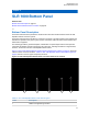


Table Of Contents
- Foreword
- General Safety and Installation Standards and Guidelines
- Declaration of Conformity
- Declaration of Compliance for the Use of Distress and Safety Frequencies
- MOTOTRBO SLR 1000 Repeater Supplemental Safety and Installation Requirements
- Environmental Information
- Document History
- Contents
- List of Figures
- List of Tables
- List of Procedures
- Related Publications
- Summary of Bands Available
- Commercial Warranty
- SLR 1000 Repeater
- SLR 1000 Satellite Receiver
- SLR 1000 Transceiver Board
- SLR 1000 Front Panel
- SLR 1000 Bottom Panel
- SLR 1000 Test Equipment And Service Aids
- SLR 1000 Performance Check or Testing
- SLR 1000 Programming and Tuning
- SLR 1000 Maintenance and Disassembly/Reassembly
- SLR 1000 Installation
- 10.1 Pre-Installation Considerations
- 10.2 SLR 1000 Repeater Package Contents
- 10.3 Mounting the SLR 1000 Repeater to a Wall or Ceiling
- 10.4 Mounting the SLR 1000 Repeater to a Pole
- 10.5 Electrical Connections
- 10.6 General Bonding and Grounding Requirements
- 10.7 General Cabling Requirements
- 10.8 Post Installation Checklist
- Appendix A: Accessories
- Appendix B: Replacement Parts Ordering
- Appendix C: Motorola Solutions Service Centers
- Appendix D: SLR 1000 Series Third-Party Controllers
- Appendix E: MOTOTRBO Repeater EME Assessment
- Glossary of Terms and Acronyms
- Alert tone
- Analog
- ASIC
- AUX
- Band
- CTCSS
- Clear
- Conventional
- CPS
- Default
- Digital
- DPL
- DSP
- EIA
- ESD
- EU
- FCC
- FM
- Frequency
- FRU
- FSK
- GNSS
- GPIO
- IC
- IF
- I/O
- kHz
- LCD
- LED
- MDC
- MHz
- MISO
- MOSI
- PA
- PC Board
- PFC
- PL
- Programming Cable
- PTT
- Radio Management
- Receiver
- Repeater
- RF
- RSSI
- Rx
- SCM
- SELV
- Signal
- SINAD
- SLR
- Spectrum
- SPI
- Squelch
- TOT
- TPL
- Transceiver
- Transmitter
- Trunking
- Tx
- UHF
- USB
- VCO
- VCTCXO
- VHF
- VIP
- VSWR
- WLAN
3.4
Station Control Subsystem
The SLR 1000 Repeater Station Control Subsystem circuitry performs the digital signal processing,
data formatting, and audio routing for the station and provides the external interfaces to the rest of the
site.
The Station Control Subsystem is described in this section. A general description, identification of
controls, indicators, and inputs/outputs, a functional block diagram, and functional theory of operation
are provided.
The Station Control consists of seven main ICs:
•
Texas Instrument DM8148 Host/DSP Processor
• EMMC Flash memory
• DDR3 memory
• Texas Instruments Power Management IC
• NOR Flash
• TI AIC3204 Codec
General controller functionality includes:
• Data and Control interface to the transceiver ICs
• Audio interface with CODEC IC
• UART interface to expansion board
• Intermodule communication (SPI, I2C)
• Ethernet port
• USB Device port
• External physical interfaces (connectors, LEDs, external references, and so on.)
• Station Reference Control
Return to Process
SLR 1000 Transceiver Board on page 49
Related Links
Station Control Audio on page 54
Station Control Interface on page 55
3.4.1
Station Control Audio
The analog audio stages of the SLR 1000 Repeater Station Control Audio are used exclusively for
external accessories connected through the bottom RJ-45 accessory connector.
The critical components of the audio circuit are the TI DM8148 processor and a Texas Instruments
AIC3204 dual channel audio codecs. Figure 12: SLR 1000 Repeater Audio Block Diagram on page
55 details the specific interconnects between the critical components.
MN003557A01-AF
Chapter 3: SLR 1000 Transceiver Board
54