
Installation Manual
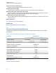


Table Of Contents
- Foreword
- General Safety and Installation Standards and Guidelines
- Declaration of Conformity
- Declaration of Compliance for the Use of Distress and Safety Frequencies
- MOTOTRBO SLR 1000 Repeater Supplemental Safety and Installation Requirements
- Environmental Information
- Document History
- Contents
- List of Figures
- List of Tables
- List of Procedures
- Related Publications
- Summary of Bands Available
- Commercial Warranty
- SLR 1000 Repeater
- SLR 1000 Satellite Receiver
- SLR 1000 Transceiver Board
- SLR 1000 Front Panel
- SLR 1000 Bottom Panel
- SLR 1000 Test Equipment And Service Aids
- SLR 1000 Performance Check or Testing
- SLR 1000 Programming and Tuning
- SLR 1000 Maintenance and Disassembly/Reassembly
- SLR 1000 Installation
- 10.1 Pre-Installation Considerations
- 10.2 SLR 1000 Repeater Package Contents
- 10.3 Mounting the SLR 1000 Repeater to a Wall or Ceiling
- 10.4 Mounting the SLR 1000 Repeater to a Pole
- 10.5 Electrical Connections
- 10.6 General Bonding and Grounding Requirements
- 10.7 General Cabling Requirements
- 10.8 Post Installation Checklist
- Appendix A: Accessories
- Appendix B: Replacement Parts Ordering
- Appendix C: Motorola Solutions Service Centers
- Appendix D: SLR 1000 Series Third-Party Controllers
- Appendix E: MOTOTRBO Repeater EME Assessment
- Glossary of Terms and Acronyms
- Alert tone
- Analog
- ASIC
- AUX
- Band
- CTCSS
- Clear
- Conventional
- CPS
- Default
- Digital
- DPL
- DSP
- EIA
- ESD
- EU
- FCC
- FM
- Frequency
- FRU
- FSK
- GNSS
- GPIO
- IC
- IF
- I/O
- kHz
- LCD
- LED
- MDC
- MHz
- MISO
- MOSI
- PA
- PC Board
- PFC
- PL
- Programming Cable
- PTT
- Radio Management
- Receiver
- Repeater
- RF
- RSSI
- Rx
- SCM
- SELV
- Signal
- SINAD
- SLR
- Spectrum
- SPI
- Squelch
- TOT
- TPL
- Transceiver
- Transmitter
- Trunking
- Tx
- UHF
- USB
- VCO
- VCTCXO
- VHF
- VIP
- VSWR
- WLAN

Varactor-tuned Preselector Filter(s)
Provides bandpass filtering of the station Receiver RF input.
Receiver Front-End Circuitry
Performs filtering, amplification, and the first down conversion of the Receiver RF signal.
Receiver-specific piece of transceiver IC Circuitry
Consists of receiver-specific parts of a transceiver IC which performs the second down conversion,
filtering, amplification, and analog-to-digital conversion of the receive signal.
Analog to Digital Converter (ADC) Circuitry
Converts analog Receiver status signals to digital format for transfer to the controller circuitry on the
Transceiver board.
Return to Process
SLR 1000 Transceiver Board on page
49
Related Links
Receiver Subsystem Specifications on page 52
3.2.1
Receiver Subsystem Specifications
The following contains the SLR 1000 Repeater receiver subsystem Radio Frequency (RF) operating
specifications.
Table 12: SLR 1000 Repeater Specifications of the Receiver Subsystem
Parameter Specifications
VHF UHF
Frequency Bands 136-174 MHz 400–512 MHz
Selectivity 25 kHz/ 12.5 kHz (TIA603E) 83 dB/55 dB 80 dB/55 dB
Selectivity 25 kHz/ 12.5 kHz (TIA603) 83 dB/68 dB 80 dB/68 dB
Selectivity 25 kHz/ 12.5 kHz (ETSI) 70 dB/ 63 dB
Sensitivity (12 dB SINAD) 0.3 uV
Sensitivity (5% BER) 0.3 uV
Intermodulation Rejection (TIA603E) 80 dB
Intermodulation Rejection (ETSI) 70 dB
Spurious Rejection (TIA603E) 85 dB
Spurious Rejection (ETSI) 75 dB
Audio Distortion <3%
FM Hum and Noise 25 kHz/ 12.5 kHz 50 dB/ 45 dB
Return to Process
Receiver Subsystem on page 51
MN003557A01-AF
Chapter
3: SLR 1000 Transceiver Board
52