
Installation Manual


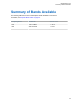

Table Of Contents
- Foreword
- General Safety and Installation Standards and Guidelines
- Declaration of Conformity
- Declaration of Compliance for the Use of Distress and Safety Frequencies
- MOTOTRBO SLR 1000 Repeater Supplemental Safety and Installation Requirements
- Environmental Information
- Document History
- Contents
- List of Figures
- List of Tables
- List of Procedures
- Related Publications
- Summary of Bands Available
- Commercial Warranty
- SLR 1000 Repeater
- SLR 1000 Satellite Receiver
- SLR 1000 Transceiver Board
- SLR 1000 Front Panel
- SLR 1000 Bottom Panel
- SLR 1000 Test Equipment And Service Aids
- SLR 1000 Performance Check or Testing
- SLR 1000 Programming and Tuning
- SLR 1000 Maintenance and Disassembly/Reassembly
- SLR 1000 Installation
- 10.1 Pre-Installation Considerations
- 10.2 SLR 1000 Repeater Package Contents
- 10.3 Mounting the SLR 1000 Repeater to a Wall or Ceiling
- 10.4 Mounting the SLR 1000 Repeater to a Pole
- 10.5 Electrical Connections
- 10.6 General Bonding and Grounding Requirements
- 10.7 General Cabling Requirements
- 10.8 Post Installation Checklist
- Appendix A: Accessories
- Appendix B: Replacement Parts Ordering
- Appendix C: Motorola Solutions Service Centers
- Appendix D: SLR 1000 Series Third-Party Controllers
- Appendix E: MOTOTRBO Repeater EME Assessment
- Glossary of Terms and Acronyms
- Alert tone
- Analog
- ASIC
- AUX
- Band
- CTCSS
- Clear
- Conventional
- CPS
- Default
- Digital
- DPL
- DSP
- EIA
- ESD
- EU
- FCC
- FM
- Frequency
- FRU
- FSK
- GNSS
- GPIO
- IC
- IF
- I/O
- kHz
- LCD
- LED
- MDC
- MHz
- MISO
- MOSI
- PA
- PC Board
- PFC
- PL
- Programming Cable
- PTT
- Radio Management
- Receiver
- Repeater
- RF
- RSSI
- Rx
- SCM
- SELV
- Signal
- SINAD
- SLR
- Spectrum
- SPI
- Squelch
- TOT
- TPL
- Transceiver
- Transmitter
- Trunking
- Tx
- UHF
- USB
- VCO
- VCTCXO
- VHF
- VIP
- VSWR
- WLAN

Chapter 1
SLR 1000 Repeater
The Motorola Solutions SLR 1000 Repeater provides a modular, flexible analog and digital station
designed for today's communication systems and for the future.
Related Links
Repeater Description
on page 29
Repeater Operating Features on page 36
Repeater Frequency Ranges and Power Levels on page 37
Repeater Specifications on page 38
Repeater Theory of Operation on page 41
Basic Repeater Level Troubleshooting – RDAC and LEDs on page 42
Repeater Model Numbering Scheme on page 44
Repeater Model Chart on page 44
1.1
Repeater Description
The station is available for use in these configurations:
• Analog Conventional
• Digital (MOTOTRBO)
• MOTOTRBO DMR Tier 2 Conventional – Single Site
• MOTOTRBO DMR Tier 2 Conventional – IP Site Connect
• MOTOTRBO Capacity Plus Trunking
• MOTOTRBO Connect Plus Trunking
• MOTOTRBO Capacity Max Trunking
• MOTOTRBO Digital Voting
NOTICE: Certain software features enabled through Radio Management can be configured with
the Online Help or with a regional representative. See the regional Ordering Guide to determine
the features available within the respective regions.
The repeater can either be configured as a stand-alone repeater or as a repeater connected to a
network, as in the case of operating in IP Site Connect mode. As a repeater, it listens on one uplink
frequency, and then re-transmits on a downlink frequency, thus providing the RF interface to the field
subscribers. When configured for analog station operation, the repeater is designed to operate with
most existing analog systems, which enables a smooth migration to the MOTOTRBO system.
When configured for digital operation, the repeater offers additional services. The digital repeater
operates in TDMA mode, which essentially divides one channel into two virtual channels using time
slots; therefore the user capacity is doubled. The repeater utilizes embedded signaling to inform the
field radios of the busy/idle status of each channel (time slot), the type of traffic, and even the source
and destination information.
See the following figures and tables for connections, ports, LEDs, and their descriptions.
MN003557A01-AF
SLR 1000 Repeater
29