
Installation Manual


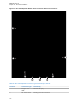
Table Of Contents
- Foreword
- General Safety and Installation Standards and Guidelines
- Declaration of Conformity
- Declaration of Compliance for the Use of Distress and Safety Frequencies
- MOTOTRBO SLR 1000 Repeater Supplemental Safety and Installation Requirements
- Environmental Information
- Document History
- Contents
- List of Figures
- List of Tables
- List of Procedures
- Related Publications
- Summary of Bands Available
- Commercial Warranty
- SLR 1000 Repeater
- SLR 1000 Satellite Receiver
- SLR 1000 Transceiver Board
- SLR 1000 Front Panel
- SLR 1000 Bottom Panel
- SLR 1000 Test Equipment And Service Aids
- SLR 1000 Performance Check or Testing
- SLR 1000 Programming and Tuning
- SLR 1000 Maintenance and Disassembly/Reassembly
- SLR 1000 Installation
- 10.1 Pre-Installation Considerations
- 10.2 SLR 1000 Repeater Package Contents
- 10.3 Mounting the SLR 1000 Repeater to a Wall or Ceiling
- 10.4 Mounting the SLR 1000 Repeater to a Pole
- 10.5 Electrical Connections
- 10.6 General Bonding and Grounding Requirements
- 10.7 General Cabling Requirements
- 10.8 Post Installation Checklist
- Appendix A: Accessories
- Appendix B: Replacement Parts Ordering
- Appendix C: Motorola Solutions Service Centers
- Appendix D: SLR 1000 Series Third-Party Controllers
- Appendix E: MOTOTRBO Repeater EME Assessment
- Glossary of Terms and Acronyms
- Alert tone
- Analog
- ASIC
- AUX
- Band
- CTCSS
- Clear
- Conventional
- CPS
- Default
- Digital
- DPL
- DSP
- EIA
- ESD
- EU
- FCC
- FM
- Frequency
- FRU
- FSK
- GNSS
- GPIO
- IC
- IF
- I/O
- kHz
- LCD
- LED
- MDC
- MHz
- MISO
- MOSI
- PA
- PC Board
- PFC
- PL
- Programming Cable
- PTT
- Radio Management
- Receiver
- Repeater
- RF
- RSSI
- Rx
- SCM
- SELV
- Signal
- SINAD
- SLR
- Spectrum
- SPI
- Squelch
- TOT
- TPL
- Transceiver
- Transmitter
- Trunking
- Tx
- UHF
- USB
- VCO
- VCTCXO
- VHF
- VIP
- VSWR
- WLAN

10.2
SLR 1000 Repeater Package Contents
Inspect the various parts and fittings within the SLR 1000 Repeater packing box. Verify that the
following contents are included.
Table 25: SLR 1000 Repeater Package Contents
Description Quantity
Safety Supplement Leaflet 1
DC Power Cable Assembly 1
Threaded M20 Seal Plugs (IP67/68) 4 (1 spare)
Cable Gland/Cord M20 Seal Cap (IP67/68) 4 (1 spare)
Wall-Mount Bracket 1
Serrated Hex Flange M6 Screws 4
SLR 1000 Repeater 1
M3 Screws 4
M4 Screws 4
Return to Process
SLR 1000 Installation on page
94
10.3
Mounting the SLR 1000 Repeater to a Wall or Ceiling
Perform this procedure to mount the SLR 1000 Repeater to either a wall or to a ceiling.
NOTICE: A wall mount provides a vertical fin orientation. This orientation is required for high
temperatures and maximum performance.
Prerequisites: Obtain the following:
•
Contents of the repeater package. See SLR 1000 Repeater Package Contents on page 101.
• Four #10/32 lag bolts (not included in the repeater package).
• Torque wrench, adjustable wrench, or a ratchet with a 10mm socket
Procedure:
1 Attached the bracket to either the wall or ceiling using four #10/32 lag bolts. See Figure 32:
Bracket Mounting Holes on page 102.
MN003557A01-AF
Chapter 10: SLR 1000 Installation
101