
Installation Guide

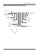
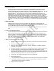
Table Of Contents
- Chapter 1 Introduction
- 1.1 Mobile Radio Description
- 1.2 Standard Configurations
- Chapter 2 Installation Details for Standard Configurations
- 2.1 Planning the Installation
- 2.2 Radio Mounting
- 2.3 Power Cable
- 2.4 Ignition Sense Cable
- 2.5 Antenna Installation
- 2.6 Microphone Hang-Up Clip
- 2.7 Completing the Installation
- Chapter 3 Options and Accessories Installation
- 3.1 Accessory Installation
- Chapter 4 Best Practices: Installation & Troubleshooting
- 4.1 Check Wiring of Ignition and Radio Ignition Sensing
- 4.2 Check Physical Installation of Radio Ground and Radio Accessory Wiring
- 4.3 Improve the Electrical Quality of the Power and Ignition Lines
- 4.4 Jump-Start the Vehicle
- 4.5 Eliminate Noise/Howling from PA Speaker
- A.1 Basic Ordering Information
- A.2 Motorola Online
- A.3 Mail Orders
- A.5 Fax Orders
- A.6 Parts Identification
- A.7 Product Customer Service
- B.1 Servicing Information
- B.2 Motorola Service Center
- B.3 Motorola Federal Technical Center
- B.4 Motorola Canadian Technical Logistics Center

Draft
vi Mobile Radio Model Numbering Scheme
Mobile Radio Model Numbering Scheme
Model No.Example : AA M 0 1 Q P H 9 J A 1 A N
Position : 1 2 3 4 5 6 7 8 9 10 11 12
Unique Model Variations
N: Standard Package
Version Letter
Feature Level
1: Mini-U
2: BNC
Primary System Type
A: Conventional
B: Trunking
C: Analog Only
Primary Operation
J: Basic
Channel Spacing
9: Variable/Programmable
Power Level
N: 1–25W
R: 1–40W
M: 10–35W
P: 25–40W
Q: 25–45W
Mobile Model Series
MOTOTRBO CM 2000 Series: 01
MOTOTRBO XPR 2000 Series: 02
Band
J : 136–174 MHz
Q: 403–470 MHz
T : 450–527 MHz
X : 450–520 MHz
U : 806–941 MHz
Physical Packages
C: Numeric Display Model
H: Monochrome Display Model
Mobile
AZ: Asia
LA: Latin America
AA: North America (except Mexico)
MD: Europe/Middle East/
Africa/Australasia