
Installation Guide

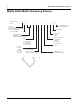
Table Of Contents
- Chapter 1 Introduction
- 1.1 Mobile Radio Description
- 1.2 Standard Configurations
- Chapter 2 Installation Details for Standard Configurations
- 2.1 Planning the Installation
- 2.2 Radio Mounting
- 2.3 Power Cable
- 2.4 Ignition Sense Cable
- 2.5 Antenna Installation
- 2.6 Microphone Hang-Up Clip
- 2.7 Completing the Installation
- Chapter 3 Options and Accessories Installation
- 3.1 Accessory Installation
- Chapter 4 Best Practices: Installation & Troubleshooting
- 4.1 Check Wiring of Ignition and Radio Ignition Sensing
- 4.2 Check Physical Installation of Radio Ground and Radio Accessory Wiring
- 4.3 Improve the Electrical Quality of the Power and Ignition Lines
- 4.4 Jump-Start the Vehicle
- 4.5 Eliminate Noise/Howling from PA Speaker
- A.1 Basic Ordering Information
- A.2 Motorola Online
- A.3 Mail Orders
- A.5 Fax Orders
- A.6 Parts Identification
- A.7 Product Customer Service
- B.1 Servicing Information
- B.2 Motorola Service Center
- B.3 Motorola Federal Technical Center
- B.4 Motorola Canadian Technical Logistics Center

Draft
List of Figures v
List of Figures
Figure 1-1 Front View of Dash Mount Trunnion for MOTOTRBO CM 2000 Series and XPR 2000
Series mobiles ...................................................................................................................... 1-1
Figure 1-2 Side View of Dash Mount with Low Profile Trunnion for MOTOTRBO CM 2000 Series
and XPR 2000 Series mobiles .............................................................................................. 1-2
Figure 1-3 Back View of the Mobile Radio ............................................................................................. 1-3
Figure 1-4 Dash Mount Configuration .................................................................................................... 1-4
Figure 2-1 Typical Dash Mount Configuration ........................................................................................ 2-1
Figure 2-2 Radio Installation (Dash Mount)............................................................................................ 2-2
Figure 2-3 Trunnion Orientation for Above or Below Mobile .................................................................. 2-3
Figure 2-4 Transmission Hump Trunnion Mounting ............................................................................... 2-4
Figure 2-5 Below Dash Trunnion Mounting............................................................................................ 2-5
Figure 2-6 Locking Kit (Optional)............................................................................................................ 2-6
Figure 2-7 Dashboard Mounting............................................................................................................. 2-7
Figure 2-8 Cabling Interconnect Diagram for Dash Mount..................................................................... 2-9
Figure 2-9 Antenna Connections on the Back of the Radio ................................................................. 2-11
Figure 2-10 Mini-UHF Connection ......................................................................................................... 2-12
Figure 3-1 Location of the Rear Accessory Connector .......................................................................... 3-1
Figure 3-2 Pin Configuration of Rear Accessory Connector for the CM 2000 Series Mobile Radios
(as viewed from the rear of the radio) ................................................................................... 3-2
Figure 3-3 Pin Configuration of Rear Accessory Connector for the XPR 2000 Series Mobile Radios
(as viewed from the rear of the radio) ................................................................................... 3-3
Figure 3-4 Emergency Switch Wiring Diagram using a CM 2000 Series Mobile Radio (a XPR 2000
Series Mobile Radio is wired the same way) ........................................................................ 3-4
Figure 3-5 Horn and Lights Wiring Diagram using a CM 2000 Series Mobile Radio (a XPR 2000
Series Mobile Radio is wired the same way) ........................................................................ 3-5
Figure 3-6 External Speaker Mounting................................................................................................... 3-6
Related Publications
MOTOTRBO CM 2300/2500 Mobile Basic Service Manual....................................................... 68009618001
MOTOTRBO XPR 2500 Mobile Basic Service Manual.............................................................. 68009620001