
Installation Guide
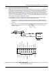


Table Of Contents
- Chapter 1 Introduction
- 1.1 Mobile Radio Description
- 1.2 Standard Configurations
- Chapter 2 Installation Details for Standard Configurations
- 2.1 Planning the Installation
- 2.2 Radio Mounting
- 2.3 Power Cable
- 2.4 Ignition Sense Cable
- 2.5 Antenna Installation
- 2.6 Microphone Hang-Up Clip
- 2.7 Completing the Installation
- Chapter 3 Options and Accessories Installation
- 3.1 Accessory Installation
- Chapter 4 Best Practices: Installation & Troubleshooting
- 4.1 Check Wiring of Ignition and Radio Ignition Sensing
- 4.2 Check Physical Installation of Radio Ground and Radio Accessory Wiring
- 4.3 Improve the Electrical Quality of the Power and Ignition Lines
- 4.4 Jump-Start the Vehicle
- 4.5 Eliminate Noise/Howling from PA Speaker
- A.1 Basic Ordering Information
- A.2 Motorola Online
- A.3 Mail Orders
- A.5 Fax Orders
- A.6 Parts Identification
- A.7 Product Customer Service
- B.1 Servicing Information
- B.2 Motorola Service Center
- B.3 Motorola Federal Technical Center
- B.4 Motorola Canadian Technical Logistics Center

Draft
4-2 Best Practices: Installation & Troubleshooting
4.2 Check Physical Installation of Radio Ground and Radio Accessory
Wiring
• Take care to scrape away paint on the chassis at the place where the ground connection is to
be made, and try to keep the ground lead as short as possible.
• Verify that the A+ lead (red) is connected directly to the positive terminal of the battery and
the ground lead (black) is connected to the vehicle’s chassis using as short of a length of
wire as is practical.
• For vehicles that have other types of electronic equipment installed (lights, flashers,
computers siren/PA and etc.), use a separate ground for the mobile radio equipment.
• Make sure that the mobile radio antenna is the minimum required distance (three feet) from
the mobile radio equipment to prevent radio frequency interference (RFI) from interfering
with the radio and/or accessories.
• Do not coil up any excess length of the A+ (red) lead. Doing this may cause a large transient
voltage to be produced when there is a high current drain (e.g. during transmit). This could
cause the radio to reset when the push-to-talk (PTT) is depressed.
• Do not coil up any excessive length of antenna cable, if possible. It may affect the radio’s
receive performance.
4.3 Improve the Electrical Quality of the Power and Ignition Lines
• Use a relay to isolate the vehicle’s ignition switch point (ACC) from the radio’s ignition sense
point. Control this relay from the vehicle’s ignition switch point (ACC). Supply a cleaner
voltage from the positive terminal of the battery into the relay, which will now be attached to
the radio’s ignition sense point. Now the ACC line toggles the relay, instead of directly
toggling the radios ignition sense line.
• Install a Power Line Filter between the A+ lead and the positive terminal of the battery. This is
intended to filter the battery power applied to the transmitter power amplifiers. Pay extra
caution to this because the series filter will introduce a negative spike when the radio
transmits that may cause problems with radio operation.
• For vehicles that use electromechanical relays to control external devices (lights, motors,
switch boxes and etc.), these relay circuits should be isolated as best as possible from the
mobile radio equipment. Also, diode suppression should be used across the relay contacts to
minimize the noise produced by the collapsing magnetic field.
• If the ignition sense switch is to be used, make sure that there is not a large voltage drop
between the A+ point (usually the positive terminal of the battery) and the ignition sense
point. In general, the voltage difference between these two points, should not be greater than
1.5 volts when all accessories/air-conditioner, etc. are turned on. Refer to the Basic Service
Manual for specifications for minimum and maximum voltage levels. Typical battery voltage
levels are 13.6V +/- 20%.