
Installation Guide
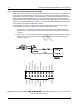
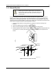


Table Of Contents
- Chapter 1 Introduction
- 1.1 Mobile Radio Description
- 1.2 Standard Configurations
- Chapter 2 Installation Details for Standard Configurations
- 2.1 Planning the Installation
- 2.2 Radio Mounting
- 2.3 Power Cable
- 2.4 Ignition Sense Cable
- 2.5 Antenna Installation
- 2.6 Microphone Hang-Up Clip
- 2.7 Completing the Installation
- Chapter 3 Options and Accessories Installation
- 3.1 Accessory Installation
- Chapter 4 Best Practices: Installation & Troubleshooting
- 4.1 Check Wiring of Ignition and Radio Ignition Sensing
- 4.2 Check Physical Installation of Radio Ground and Radio Accessory Wiring
- 4.3 Improve the Electrical Quality of the Power and Ignition Lines
- 4.4 Jump-Start the Vehicle
- 4.5 Eliminate Noise/Howling from PA Speaker
- A.1 Basic Ordering Information
- A.2 Motorola Online
- A.3 Mail Orders
- A.5 Fax Orders
- A.6 Parts Identification
- A.7 Product Customer Service
- B.1 Servicing Information
- B.2 Motorola Service Center
- B.3 Motorola Federal Technical Center
- B.4 Motorola Canadian Technical Logistics Center

Draft
Chapter 4 Best Practices: Installation & Troubleshooting
In this section are Motorola recommended vehicle installation practices that can address or prevent
many issues, including:
• Radio circuit damage due to over voltage condition
• Radio/Accessories "lock up"
• Radio/Accessories change state/lock-up when radio PTT is depressed
• Radio intermittently resets
• Alternator whine present when transmitting with engine running
• Radio/Accessories turn themselves on/off
4.1 Check Wiring of Ignition and Radio Ignition Sensing
• If it is required to turn the radio on and off via the ignition sense switch, in addition to the control
head’s on/off switch, connect the ignition sense lead to the accessory terminal from the ignition
switch (usually in the vehicle’s fuse panel under accessory or radio).
NOTE: Motorola recommends protecting or isolating the radio’s ignition sense input from voltage spikes
in excess of +/- 40 VDC. Such spikes can be hundreds of volts in amplitude and are common in
larger vehicles (utility trucks, buses and etc.), especially when the source is common to a
solenoid coil. A triggerable oscilloscope is required to determine the existence of such spikes as
most voltmeters cannot measure in short duration (< 1 msec). If the condition of the intended
ignition sense source is unknown, Motorola recommends isolating the source from the radio with
a relay or the use of a suppression diode wired between the source and ground. Any high current
suppression diode (i.e. MR2535) with a breakdown voltage of between 18 and 40 volts will
suffice. A suitable diode kit is available from Motorola parts, kit number HLN6325_.
• If it is required to have the radio power up only via the control head’s on/off switch, then connect
the ignition sense lead directly to the positive terminal of the battery. This will mean the ignition
sense will always be ignored and a re-wiring will be necessary in the future if the operator
chooses any ignition sense CPS setting.