
Installation Guide
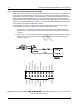
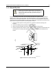


Table Of Contents
- Chapter 1 Introduction
- 1.1 Mobile Radio Description
- 1.2 Standard Configurations
- Chapter 2 Installation Details for Standard Configurations
- 2.1 Planning the Installation
- 2.2 Radio Mounting
- 2.3 Power Cable
- 2.4 Ignition Sense Cable
- 2.5 Antenna Installation
- 2.6 Microphone Hang-Up Clip
- 2.7 Completing the Installation
- Chapter 3 Options and Accessories Installation
- 3.1 Accessory Installation
- Chapter 4 Best Practices: Installation & Troubleshooting
- 4.1 Check Wiring of Ignition and Radio Ignition Sensing
- 4.2 Check Physical Installation of Radio Ground and Radio Accessory Wiring
- 4.3 Improve the Electrical Quality of the Power and Ignition Lines
- 4.4 Jump-Start the Vehicle
- 4.5 Eliminate Noise/Howling from PA Speaker
- A.1 Basic Ordering Information
- A.2 Motorola Online
- A.3 Mail Orders
- A.5 Fax Orders
- A.6 Parts Identification
- A.7 Product Customer Service
- B.1 Servicing Information
- B.2 Motorola Service Center
- B.3 Motorola Federal Technical Center
- B.4 Motorola Canadian Technical Logistics Center

Draft
3-5 Options and Accessories Installation Accessory Installation
3.1.2 Horn and Lights (External Alarm) Relay
Allows the user to be alerted to an incoming call when away from the vehicle. The vehicle's horn or
lights or both are used depending on which option is connected to the accessory port. When the
radio receives a call alert or emergency alarm/call, there is a delay before activating the horn and/or
lights. The delay is programmable using the Horn & Lights Delay Time feature in the CPS. Once
activated, the Horn and/or Lights remain active depending on the option selected. The Horn & Lights
feature can be toggled between ON or OFF, via a short or long programmable button press (Horn &
Lights On/Off) or Horn/Lights (Utilities Menu) feature.
For installations that use the horn/lights option, select a suitable location for mounting (normally
under the dash) and, referring to Figure 3-5, perform the following procedure:
1. Horn Relay – Connect the relay contacts across the horn ring switch, typically found in the
steering column. Connect the two control wires (female pins) into locations 4 and 7 of the
connector.
2. Lights Relay – Connect the relay across the headlamp ON/OFF switch, typically found in the
steering column. Connect the two control wires (female pins) into locations 4 and 7 of the
accessory connector.
Figure 3-5 Horn and Lights Wiring Diagram using a CM 2000 Series Mobile Radio (a XPR 2000 Series Mobile
Radio is wired the same way)
Y
4
7
SPEAKER-
GPI_1 (PTT)
EXT MIC AUDIO
EMERGENCY SW
FLAT TX AUDIO
IGNITION SENSE
SWB+
RSSI
RX AUDIO
GPIO_4
SPEAKER+
GPIO_8
GPIO_7
VIP_1 (EXT ALARM)
GROUND
UART CTS
(Motorola Use Only)
911191735
17
13 15
12820 2 6 814 14 16
10
GROUND
UART RX
(Motorola Use Only)
UART TX
(Motorola Use Only)
UART RTS
(Motorola Use Only)