
Installation Guide
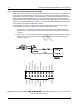
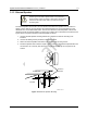


Table Of Contents
- Chapter 1 Introduction
- 1.1 Mobile Radio Description
- 1.2 Standard Configurations
- Chapter 2 Installation Details for Standard Configurations
- 2.1 Planning the Installation
- 2.2 Radio Mounting
- 2.3 Power Cable
- 2.4 Ignition Sense Cable
- 2.5 Antenna Installation
- 2.6 Microphone Hang-Up Clip
- 2.7 Completing the Installation
- Chapter 3 Options and Accessories Installation
- 3.1 Accessory Installation
- Chapter 4 Best Practices: Installation & Troubleshooting
- 4.1 Check Wiring of Ignition and Radio Ignition Sensing
- 4.2 Check Physical Installation of Radio Ground and Radio Accessory Wiring
- 4.3 Improve the Electrical Quality of the Power and Ignition Lines
- 4.4 Jump-Start the Vehicle
- 4.5 Eliminate Noise/Howling from PA Speaker
- A.1 Basic Ordering Information
- A.2 Motorola Online
- A.3 Mail Orders
- A.5 Fax Orders
- A.6 Parts Identification
- A.7 Product Customer Service
- B.1 Servicing Information
- B.2 Motorola Service Center
- B.3 Motorola Federal Technical Center
- B.4 Motorola Canadian Technical Logistics Center

Draft
Options and Accessories Installation Accessory Installation 3-4
3.1.1 Emergency Pushbutton or Footswitch Installation
Mount the emergency pushbutton (Motorola part number RLN4857_) or the footswitch (Motorola part
number RLN4836AR_) using the hardware that comes with the kit. Press the terminal into the
accessory connector housing. Connect the emergency switch wires to pins 9 and 7 (see
Figure 3-4). Route the finished cable from the switch location to the control head location.
Figure 3-4 Emergency Switch Wiring Diagram using a CM 2000 Series Mobile Radio (a XPR 2000 Series
Mobile Radio is wired the same way)
ACCESSORY
CONNEC T O R
PIN 9
PIN 7
NOTE 1
SPS T NORMAL L Y OPEN
EMERGENC Y SWITC H
SPEAKER-
GPI_1 (PTT)
EXT MIC AUDIO
EMERGENCY SW
FLAT TX AUDIO
IGNITION SENSE
SWB+
RSSI
RX AUDIO
GPIO_4
SPEAKER+
GPIO_8
GPIO_7
VIP_1 (EXT ALARM)
GROUND
UART CTS
(Motorola Use Only)
911191735
17
13 15
12820 2 6 814 14 16
10
GROUND
UART RX
(Motorola Use Only)
UART TX
(Motorola Use Only)
UART RTS
(Motorola Use Only)