
Installation Guide
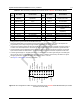
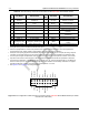
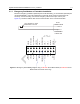
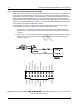
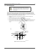


Table Of Contents
- Chapter 1 Introduction
- 1.1 Mobile Radio Description
- 1.2 Standard Configurations
- Chapter 2 Installation Details for Standard Configurations
- 2.1 Planning the Installation
- 2.2 Radio Mounting
- 2.3 Power Cable
- 2.4 Ignition Sense Cable
- 2.5 Antenna Installation
- 2.6 Microphone Hang-Up Clip
- 2.7 Completing the Installation
- Chapter 3 Options and Accessories Installation
- 3.1 Accessory Installation
- Chapter 4 Best Practices: Installation & Troubleshooting
- 4.1 Check Wiring of Ignition and Radio Ignition Sensing
- 4.2 Check Physical Installation of Radio Ground and Radio Accessory Wiring
- 4.3 Improve the Electrical Quality of the Power and Ignition Lines
- 4.4 Jump-Start the Vehicle
- 4.5 Eliminate Noise/Howling from PA Speaker
- A.1 Basic Ordering Information
- A.2 Motorola Online
- A.3 Mail Orders
- A.5 Fax Orders
- A.6 Parts Identification
- A.7 Product Customer Service
- B.1 Servicing Information
- B.2 Motorola Service Center
- B.3 Motorola Federal Technical Center
- B.4 Motorola Canadian Technical Logistics Center

Draft
3-3 Options and Accessories Installation Accessory Installation
1
Pulling this line to ground activates the Ext Mic Audio input
2
Fixed level (independent of volume level) received audio signal, including alert tones. Flat or de-emphasis are
programmed by CPS. Output voltage is approximately 330 mVrms per 1 kHz of deviation.
3
This input is for injecting signals into the transmit path that should not be filtered; for example, the analog output of
a modem. The nominal input level is 150 mVrms for 60% deviation and the input impedance is greater than 25k.
4
This microphone signal is independent of the microphone signal on the front microphone connector. The nominal
input level is 80 mVrms for 60% deviation. The DC impedance is 660 ohms and the AC impedance is 560 ohms.
5
A receive signal strength of –120 dBm gives about 1.12 Vdc at pin 15. A receive signal strength of –60 dBm gives
about 2.44 Vdc at pin 15. The receive signal strength for levels in between can be linearly calculated. For signals
strengths greater than –60 dbm, the voltage stays relatively flat at ~ 2.44 Vdc.
6
See Figure 2-2 and Figure 2-8 for wiring information.
Figure 3-3 Pin Configuration of Rear Accessory Connector for the XPR 2000 Series Mobile Radios (as viewed
from the rear of the radio)
Table 3-2 Rear Accessory Connector Pin Functions for the XPR 2000 Series Mobile Radios
Pin
No.
Pin Name Pin Function
Pin
No.
Pin Name Pin Function
1 Speaker–
Speaker – (3.2 ohm minimum
impedance)
11
Rx Audio Receive Live Audio
2
2 Ext Mic Audio
Rear External Microphone
Input
4
12 GPIO_7 5V Level GPIO
3 GPI_1 (PTT) 5V Level GPI, PTT Input
1
13 SWB+ Switched Battery Voltage
4 VIP_1 (Ext Alarm) 12V Supply, External Alarm 14 GPIO_8 5V Level GPIO
5 Flat Tx Audio Data Input
3
15 RSSI
Receive Signal Strength
Indicator
5
6 GPIO_3 5V Level GPIO 16 Speaker+
Speaker + (3.2 ohm minimum
impedance)
7 Ground Ground 17 USB D+ Universal Serial Bus Data +
8 GPIO_4 5V Level GPIO 18 USB D– Universal Serial Bus Data –
9 Emergency SW Emergency Switch Input 19 VBUS
USB Power (5V from USB
Cable)
10 Ignition Sense Ignition Sense Input
6
20 USB Ground Universal Serial Bus Ground
SPEAKER-
GPI_1 (PTT)
EXT MIC AUDIO
EMERGENCY SW
FLAT TX AUDIO
IGNITION SENSE
SWB+
RSSI
RX AUDIO
GPIO_4
SPEAKER+
GPIO_8
GPIO_7
VIP_1 (EXT ALARM)
USB GROUND
GPIO_3
9119 11735 1713 15
12820 2 641814 16
10
GROUND
USB D-
USB D+
VBUS