
Installation Guide
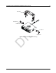
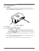
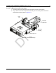
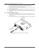
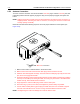
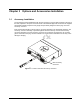
Table Of Contents
- Chapter 1 Introduction
- 1.1 Mobile Radio Description
- 1.2 Standard Configurations
- Chapter 2 Installation Details for Standard Configurations
- 2.1 Planning the Installation
- 2.2 Radio Mounting
- 2.3 Power Cable
- 2.4 Ignition Sense Cable
- 2.5 Antenna Installation
- 2.6 Microphone Hang-Up Clip
- 2.7 Completing the Installation
- Chapter 3 Options and Accessories Installation
- 3.1 Accessory Installation
- Chapter 4 Best Practices: Installation & Troubleshooting
- 4.1 Check Wiring of Ignition and Radio Ignition Sensing
- 4.2 Check Physical Installation of Radio Ground and Radio Accessory Wiring
- 4.3 Improve the Electrical Quality of the Power and Ignition Lines
- 4.4 Jump-Start the Vehicle
- 4.5 Eliminate Noise/Howling from PA Speaker
- A.1 Basic Ordering Information
- A.2 Motorola Online
- A.3 Mail Orders
- A.5 Fax Orders
- A.6 Parts Identification
- A.7 Product Customer Service
- B.1 Servicing Information
- B.2 Motorola Service Center
- B.3 Motorola Federal Technical Center
- B.4 Motorola Canadian Technical Logistics Center

Draft
Installation Details for Standard Configurations Microphone Hang-Up Clip 2-13
2.6 Microphone Hang-Up Clip
2.6.1 Standard Hang-Up Clip
The hang-up clip must be within reach of the operator(s). Measure this distance before actually
mounting the bracket. Since the bracket has a positive-detent action, the microphone can be
mounted in any position. The microphone hang-up clip must be grounded.
Use the hang-up clip as a template to locate the mounting holes. To avoid interference when
removing the microphone, install the flathead screw in the top clip hole.
2.7 Completing the Installation
Complete the installation by connecting the power wires and plugging in the microphone cable to the
mobile.