
Installation Guide
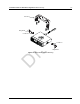
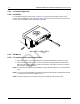
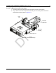
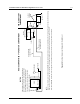
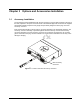
Table Of Contents
- Chapter 1 Introduction
- 1.1 Mobile Radio Description
- 1.2 Standard Configurations
- Chapter 2 Installation Details for Standard Configurations
- 2.1 Planning the Installation
- 2.2 Radio Mounting
- 2.3 Power Cable
- 2.4 Ignition Sense Cable
- 2.5 Antenna Installation
- 2.6 Microphone Hang-Up Clip
- 2.7 Completing the Installation
- Chapter 3 Options and Accessories Installation
- 3.1 Accessory Installation
- Chapter 4 Best Practices: Installation & Troubleshooting
- 4.1 Check Wiring of Ignition and Radio Ignition Sensing
- 4.2 Check Physical Installation of Radio Ground and Radio Accessory Wiring
- 4.3 Improve the Electrical Quality of the Power and Ignition Lines
- 4.4 Jump-Start the Vehicle
- 4.5 Eliminate Noise/Howling from PA Speaker
- A.1 Basic Ordering Information
- A.2 Motorola Online
- A.3 Mail Orders
- A.5 Fax Orders
- A.6 Parts Identification
- A.7 Product Customer Service
- B.1 Servicing Information
- B.2 Motorola Service Center
- B.3 Motorola Federal Technical Center
- B.4 Motorola Canadian Technical Logistics Center

Draft
2-12 Installation Details for Standard Configurations Antenna Installation
2.5.3 Antenna Connection
To ensure a secure connection of an antenna cable's mini-UHF plug to a radio's mini-UHF jack, their
interlocking features must be properly engaged. If they are not properly engaged, the system will
loosen.
NOTE: Applying excessive force with a tool can cause damage to the antenna or the connector (e.g.,
stripping threads, deforming the collar or connector, or causing the connector to twist in the
housing opening and break).
Motorola recommends the following sequence to ensure proper attachment of the system (see
Figure 2-10):
1. Make sure that there is sufficient slack in the antenna cable.
2. Make sure that the collar of the antenna cable plug is loose and does not bind.
3. Slide the collar back against the flange. Insert the antenna cable plug’s pin fully into the radio
jack, but do not engage the threads.
4. Ensure that the plug’s and jack’s interlocking features are fully seated. Check this by grasping
the crimp on the cable jack, rotating the cable, and noting any movement. If the features are
seated correctly, there should be NO movement.
5. Finger-tighten the antenna cable plug’s collar onto the radio’s jack.
6. Give a final tug, by hand, to the collar, and retighten by hand as firmly as possible.
7. Use the rubber-coated pliers to grip the plug’s knurled collar, then turn clockwise to tighten
the collar. It should take 1/4 turn or less. Turning counterclockwise loosens the collar.
NOTE: Overtightening the collar can damage the connector and the radio.
Figure 2-10 Mini-UHF Connection
Flange
Collar Pulled
Back to Flange
Mini UHF
Jack
Cable