
Installation Guide
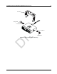
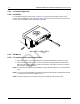
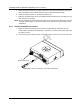
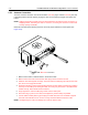
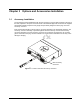
Table Of Contents
- Chapter 1 Introduction
- 1.1 Mobile Radio Description
- 1.2 Standard Configurations
- Chapter 2 Installation Details for Standard Configurations
- 2.1 Planning the Installation
- 2.2 Radio Mounting
- 2.3 Power Cable
- 2.4 Ignition Sense Cable
- 2.5 Antenna Installation
- 2.6 Microphone Hang-Up Clip
- 2.7 Completing the Installation
- Chapter 3 Options and Accessories Installation
- 3.1 Accessory Installation
- Chapter 4 Best Practices: Installation & Troubleshooting
- 4.1 Check Wiring of Ignition and Radio Ignition Sensing
- 4.2 Check Physical Installation of Radio Ground and Radio Accessory Wiring
- 4.3 Improve the Electrical Quality of the Power and Ignition Lines
- 4.4 Jump-Start the Vehicle
- 4.5 Eliminate Noise/Howling from PA Speaker
- A.1 Basic Ordering Information
- A.2 Motorola Online
- A.3 Mail Orders
- A.5 Fax Orders
- A.6 Parts Identification
- A.7 Product Customer Service
- B.1 Servicing Information
- B.2 Motorola Service Center
- B.3 Motorola Federal Technical Center
- B.4 Motorola Canadian Technical Logistics Center

Draft
2-10 Installation Details for Standard Configurations Ignition Sense Cable
2.4 Ignition Sense Cable
Motorola supplies an ignition sense cable and recommends that it be used with every mobile
installation. The ignition sense cable allows the radio to be turned on and off with the vehicle ignition
switch, and allows the radio to “remember” the state of the radio on/off switch, even if it is changed
while the vehicle is off.
• For radio ON/OFF control independent of the ignition switch, connect the red ignition cable (pin
10 of accessory connector) to “battery hot” at the vehicle fuse block.
• For radio ON/OFF control via the ignition switch, connect the red ignition cable to “ignition” at
the fuse block.
The ignition sense cable uses either a 3-Amp (P/N 6500139764) or 4-Amp (P/N 6580283E02) fuse.
For other considerations when connecting the ignition cable, see the MOTOTRBO CM 2300/2500
Basic Service Manual (Motorola publication part number 68009618001 or XPR 2500 Basic Service
Manual (Motorola publication part number 68009620001).
2.5 Antenna Installation
IMPORTANT NOTE: To assure optimum performance and compliance with RF Energy Safety
standards, these antenna installation guidelines and instructions are limited to
metal-body vehicles with appropriate ground planes and take into account the
potential exposure of back seat passengers and bystanders outside the
vehicle.
NOTE: For mobile radios with rated power of 7 watts or less, the only installation restrictions are to
use only Motorola approved antennas and install the antenna externally on metal body
vehicles. For mobile radios with rated power greater than 7 Watts, always adhere to all the
guidelines and restrictions in Section 2.5.1 below.
2.5.1 Selecting an Antenna Site/Location on a Metal Body Vehicle
1. External Installation - Check the requirements of the antenna supplier and install the vehicle
antenna external to a metal body vehicle in accordance with those requirements.
2. Roof Top - For optimum performance and compliance with RF Energy Safety Standards,
mount the antenna in the center of the roof.
3. Trunk Lid - On some vehicles with clearly defined, flat trunk lids, the antennas of some radio
models (see restrictions below) can also be mounted on the center area of the trunk lid. For
vehicles without clearly defined, flat trunk lids (such as hatchback autos, sport utility vehicles,
and pick-up trucks), mount the antenna in the center of the roof.
BEFORE INSTALLING AN ANTENNA ON THE TRUNK LID,
- Be sure that the distance from the antenna location on the trunk lid will be at least
85 cm (33 in.) from the front surface of the rear seat-back to assure compliance with RF
Energy Safety standards.
- Ensure that the trunk lid is grounded by connecting grounding straps between the trunk lid
and the vehicle chassis.
NOTE: If these conditions cannot be satisfied, then mount the antenna on the roof top.
4. Mounting restrictions for certain radio models - For all VHF and UHF models with the
output power set to 30 watts or higher, the ¼ wave antenna shall be mounted only in the
center area of the roof, not on the trunk lid, to assure compliance with RF Energy Safety
standards.