
Installation Guide
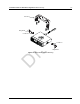
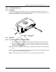
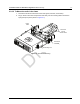
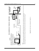
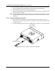
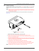
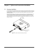
Table Of Contents
- Chapter 1 Introduction
- 1.1 Mobile Radio Description
- 1.2 Standard Configurations
- Chapter 2 Installation Details for Standard Configurations
- 2.1 Planning the Installation
- 2.2 Radio Mounting
- 2.3 Power Cable
- 2.4 Ignition Sense Cable
- 2.5 Antenna Installation
- 2.6 Microphone Hang-Up Clip
- 2.7 Completing the Installation
- Chapter 3 Options and Accessories Installation
- 3.1 Accessory Installation
- Chapter 4 Best Practices: Installation & Troubleshooting
- 4.1 Check Wiring of Ignition and Radio Ignition Sensing
- 4.2 Check Physical Installation of Radio Ground and Radio Accessory Wiring
- 4.3 Improve the Electrical Quality of the Power and Ignition Lines
- 4.4 Jump-Start the Vehicle
- 4.5 Eliminate Noise/Howling from PA Speaker
- A.1 Basic Ordering Information
- A.2 Motorola Online
- A.3 Mail Orders
- A.5 Fax Orders
- A.6 Parts Identification
- A.7 Product Customer Service
- B.1 Servicing Information
- B.2 Motorola Service Center
- B.3 Motorola Federal Technical Center
- B.4 Motorola Canadian Technical Logistics Center

Draft
2-8 Installation Details for Standard Configurations Power Cable
2.2.3.3 To Remove the radio from the frame
1. Push the two demounting tools through the openings in the frame until the two springs
release the radio.
2. Slide out the radio.
NOTE: The fixing tabs should be checked for tightness each time the radio is removed. The tabs are
easily tightened by twisting a large flat-head screwdriver in the slot behind the tabs.
NOTE: The frame is not designed for regular mounting and demounting.
2.3 Power Cable
Route the red radio power cable from the radio to the vehicle’s battery compartment, using accepted
industry methods and standards. Be sure to grommet the firewall hole to protect the cable. Remove
the 15-Amp (part number 6580283E06) or 20-Amp (part number 6580283E07) fuse from the
fuseholder and connect the red lead of the radio power cable to the positive battery terminal using
the hardware provided as shown in Figure 2-8. Connect the black lead to a convenient solid chassis
ground point. DO NOT connect the black lead directly to the battery’s negative terminal.