
Installation Guide
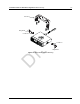
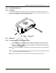
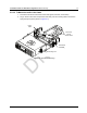
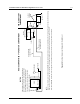
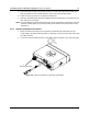
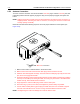
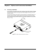
Table Of Contents
- Chapter 1 Introduction
- 1.1 Mobile Radio Description
- 1.2 Standard Configurations
- Chapter 2 Installation Details for Standard Configurations
- 2.1 Planning the Installation
- 2.2 Radio Mounting
- 2.3 Power Cable
- 2.4 Ignition Sense Cable
- 2.5 Antenna Installation
- 2.6 Microphone Hang-Up Clip
- 2.7 Completing the Installation
- Chapter 3 Options and Accessories Installation
- 3.1 Accessory Installation
- Chapter 4 Best Practices: Installation & Troubleshooting
- 4.1 Check Wiring of Ignition and Radio Ignition Sensing
- 4.2 Check Physical Installation of Radio Ground and Radio Accessory Wiring
- 4.3 Improve the Electrical Quality of the Power and Ignition Lines
- 4.4 Jump-Start the Vehicle
- 4.5 Eliminate Noise/Howling from PA Speaker
- A.1 Basic Ordering Information
- A.2 Motorola Online
- A.3 Mail Orders
- A.5 Fax Orders
- A.6 Parts Identification
- A.7 Product Customer Service
- B.1 Servicing Information
- B.2 Motorola Service Center
- B.3 Motorola Federal Technical Center
- B.4 Motorola Canadian Technical Logistics Center

Draft
2-6 Installation Details for Standard Configurations Radio Mounting
2.2.2 Locking Kit (Optional)
2.2.2.1 All Radios
If an optional locking kit is used (shown in Figure 2-6), position the lock bottom housing on the
trunnion before installing the radio mounting screws. Then slip the top lock housing on and remove
the key. You can install the lock on either side of the radio.
2.2.3 DIN Mount
2.2.3.1 To install the frame into the dashboard
1. Open up the radio cut-out in the dashboard to ISO7736 specification (182 mm x 53 mm).
2. Insert the mounting frame into the cut-out and retain it by bending back the relevant fixing
tabs (using all 6 where possible). Check the orientation of the frame is correct by ensuring
that the word “TOP” is uppermost.
NOTE: The tabs are easily bent back by twisting a large flat-head screwdriver in the slot behind the
tabs.
NOTE: For a more secure installation the frame should also be secured with the appropriate number
of screws to the mounting conditions (min. 1).
NOTE: The demounting tool can be used as an aid to mounting as well as demounting.
Figure 2-6 Locking Kit (Optional)
L o c k